Correcting circuit and real-time clock circuit
A technology for calibrating circuits and real-time clocks, applied in the field of electronics, can solve problems such as waste of MCU resources and inability to correct chips, and achieve the effect of saving MCU resources
- Summary
- Abstract
- Description
- Claims
- Application Information
AI Technical Summary
Problems solved by technology
Method used
Image

Examples
Embodiment 1
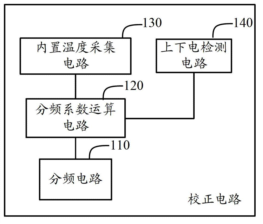
[0030] figure 2It is a structural schematic diagram of Embodiment 1 of the correction circuit of the present invention. The circuit of this embodiment is suitable for calibration of a quartz crystal oscillator that provides timing pulses to the RTC. refer to figure 2 The correction circuit includes: a frequency division circuit 110, a frequency division coefficient calculation circuit 120, a built-in temperature acquisition circuit 130, and a power-on and power-on detection circuit 140, and the above-mentioned circuits are all integrated in the chip; the built-in temperature acquisition circuit 130 is used to collect the temperature of the chip Temperature; power on and off detection circuit 140, used to detect whether the chip is powered off; frequency division coefficient calculation circuit 120, used to collect according to the built-in temperature acquisition circuit 130 when the power on and off detection circuit detects that the chip is powered off. According to the ...
Embodiment 2
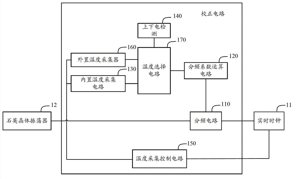
[0036] image 3 It is a schematic structural diagram of the second embodiment of the correction circuit of the present invention, refer to image 3 On the basis of the first embodiment above, in order to realize the correction when the chip is powered on, the power-on and power-on detection circuit 140 in this embodiment is also used to detect whether the chip is powered on, and the correction circuit also includes: an external temperature collector 160 , used to collect the temperature of the quartz crystal in the quartz crystal oscillator 12 outside the chip; the temperature selection circuit 170, with the built-in temperature acquisition circuit 130, the external temperature acquisition device 160, the power-up and down-power detection circuit 140, and the frequency division coefficient calculation circuit 120 connection, for when the power-on and power-off detection circuit 140 detects that the chip is powered off, the temperature of the chip collected by the built-in temp...
Embodiment 3
[0041] Figure 4 It is a schematic structural diagram of the third embodiment of the correction circuit of the present invention, refer to Figure 4 On the basis of the first embodiment above, in order to realize the correction when the chip is powered on, the power-on and power-on detection circuit 140 in this embodiment is also used to detect whether the chip is powered on, and the correction circuit also includes: a temperature deviation calculation circuit 180, Respectively connected with built-in temperature acquisition circuit 130, power on and off detection circuit 140, frequency division coefficient calculation circuit 120; temperature deviation calculation circuit 180, for when power on and off detection circuit 140 detects that the chip is powered off, the built-in temperature acquisition circuit The temperature of the chip collected by 130 is output to the frequency division coefficient operation circuit 120, and when the power-on detection circuit 140 detects that ...
PUM
 Abstract
Description
Claims
Application Information
 - R&D
- Intellectual Property
- Life Sciences
- Materials
- Tech Scout
- Unparalleled Data Quality
- Higher Quality Content
- 60% Fewer Hallucinations
Browse by: Latest US Patents, China's latest patents, Technical Efficacy Thesaurus, Application Domain, Technology Topic, Popular Technical Reports.
© 2025 PatSnap. All rights reserved.Legal|Privacy policy|Modern Slavery Act Transparency Statement|Sitemap|About US| Contact US: help@patsnap.com