Composite type rotary encoder and measurement method thereof
A rotary encoder and composite technology, applied in the field of rotary encoders, can solve the problems of binary code disc production error, increasing n value, code track advance or delay, etc.
- Summary
- Abstract
- Description
- Claims
- Application Information
AI Technical Summary
Problems solved by technology
Method used
Image
Examples
Embodiment 1
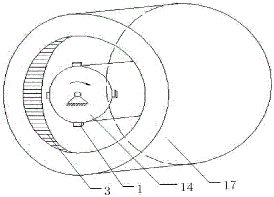
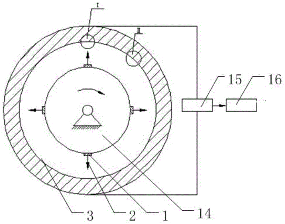
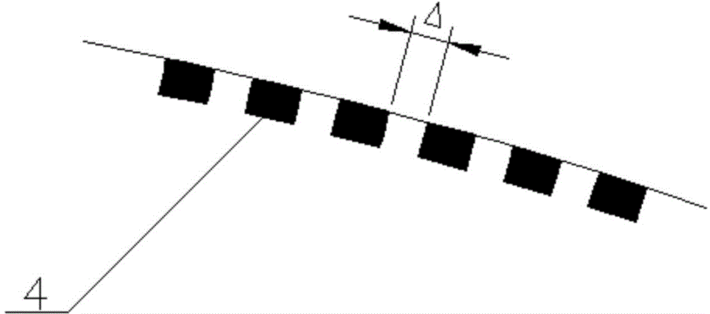
[0084] refer to Figure 1~Figure 5 , a composite rotary encoder, used to measure the rotation angle of the servo motor, including an optical system, a circular encoder ring 17, a rotating shaft 14, a data acquisition module 15 and a data processing unit 16, the optical system includes a plurality of uniformly distributed The light source module 1 on the surface of the rotating shaft 14, the circular encoding ring 17 is fixed on the frame of the servo motor, the rotating shaft 14 is connected with the servo motor through a brush and is located in the circular encoding ring 17, the circular encoding ring 17 and the rotating shaft 14 It is coaxially installed, and the circular coding ring 17 is provided with a plurality of relative code tracks and a plurality of absolute code track groups in turn on the inner surface 3 of the ring parallel to its axis;
[0085] A plurality of relative code tracks includes multiple groups of photoelectric sensors 4 evenly distributed around the ci...
Embodiment 2
[0100] A method for measuring a composite rotary encoder in Embodiment 1, comprising:
[0101] S1. Install a rotary encoder on the servo motor to be tested;
[0102] S2. The rotating shaft 14 of the rotary encoder rotates under the drive of the servo motor, so that the light emitted by the light source module 1 scans and irradiates a plurality of relative code tracks and a plurality of absolute code track groups on the circular encoding ring 17;
[0103] S3. The photoelectric sensor 4 on each relative code track successively senses light under the irradiation of light and generates a group of time sequence pulse signals, and the photoelectric sensor 4 on each absolute code track successively senses light under the irradiation of light and generates a group of coded pulse signals;
[0104] S4, the data acquisition module 15 collects the timing pulse signal and the encoded pulse signal and sends it to the data processing unit 16;
[0105] S5. The data processing unit 16 counts ...
Embodiment 3
[0113] This embodiment is basically similar to Embodiment 2, the difference is that step S5 is specifically:
[0114] The data processing unit 16 counts the timing pulses in the timing pulse signal after receiving the timing pulse signal, and calculates the rotation angle of the servo motor after obtaining the real-time count total value K, and then calculates the rotation speed of the servo motor;
[0115] After the data processing unit 16 receives multiple sets of coded pulse signals, according to the calculated rotational speed of the servo motor, select the coded pulse signal of the absolute code channel group corresponding to the rotational speed, and then count the coded pulses in the coded pulse signal Obtain the real-time quantity of encoding pulses, and judge whether the multiple relationship between the real-time quantity and the real-time count total value K is equal to the quantity multiple relationship between the corresponding absolute code track and the photoelec...
PUM
 Abstract
Description
Claims
Application Information
 - R&D
- Intellectual Property
- Life Sciences
- Materials
- Tech Scout
- Unparalleled Data Quality
- Higher Quality Content
- 60% Fewer Hallucinations
Browse by: Latest US Patents, China's latest patents, Technical Efficacy Thesaurus, Application Domain, Technology Topic, Popular Technical Reports.
© 2025 PatSnap. All rights reserved.Legal|Privacy policy|Modern Slavery Act Transparency Statement|Sitemap|About US| Contact US: help@patsnap.com


