Underwater low-resistance pile foundation low-strain dynamic monitoring device

A low-resistance, pile-based technology, used in infrastructure engineering, infrastructure testing, construction, etc., can solve the problems of complex and difficult operation, high difficulty, decreased probe sensitivity, etc., and achieve the effect of saving test costs and reducing obstacles.

Active Publication Date: 2015-03-25
天津中玻北方新材料有限责任公司
View PDF5 Cites 2 Cited by
  • Summary
  • Abstract
  • Description
  • Claims
  • Application Information

AI Technical Summary

Problems solved by technology

However, the existing low-strain dynamic measuring instrument is not suitable for use in deep water. On the one hand, when using the dynamic measuring instrument for detection, two people are generally required to cooperate. One person presses the probe on the pile head, and the other hand The hand hammer or power hammer hits the top of the pile to generate a stress wave, and another person initially judges whether the curve is qualified through the display of the pile detector connected to the probe, and records the corresponding pile number, and then uses special software to further analyze the data; On the other hand, in the deep water high pressure environment, the use of artificial diving for low-strain operations is not only high in labor costs, complicated and difficult to operate, but also the probe of the dynamic tester will seep into the water under the high pressure of deep water, resulting in a decrease in the sensitivity of the probe, and the low-strain curve knocked out Distorted messy, poor results
Expensive labor costs, high difficulty of detection and poor detection effect severely limit the application of low-strain dynamic detectors in marine and river-sea pile foundation detection

Method used


Image

  • Underwater low-resistance pile foundation low-strain dynamic monitoring device
  • Underwater low-resistance pile foundation low-strain dynamic monitoring device
  • Underwater low-resistance pile foundation low-strain dynamic monitoring device

Examples


Embodiment Construction

[0021] Embodiments of the present invention will be further described in detail below in conjunction with the accompanying drawings.

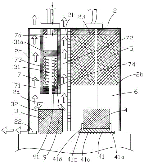
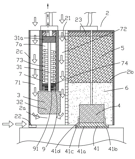
[0022] Figure 1 to Figure 4 Shown is the structural representation of the present invention.

[0023] The reference signs are: data processor 1, controller 11, stress wave generating and receiving device 2, left cavity 2a, right cavity 2b, housing 2c, waterproof interlayer 21, balance feet 22, glue layer 23, Hammer 3, hammer handle 31, rubber body 31a, hammer head 32, stress wave receiving probe 4, pressure isolation block 41, pressure isolation hard layer 41a, adhesive glue layer 41b, sealing shoulder 41c, sealing ring 41d, Counterweight 5, damping layer 6, pushing chamber 7, pushing chamber 7a, left waterway 71, right waterway 72, spring 73, rubber sealing block 74, pumping and injecting device 8, high-pressure gas injecting machine 81, air pump 82, sealing flange 9, sealing floating ring 91.

[0024] Such as Figure 1 to Figure 4 As sho...


PUM


Abstract

The invention discloses an underwater low-resistance pile foundation low-strain dynamic monitoring device. A driving hammer and a stress wave receiving probe are integrated into a stress wave generation receiving device, and meanwhile automation of falling and lifting of the driving hammer is achieved; the stress wave generation receiving device is fixed to the top of a pile foundation through the combination of a balancing weight and a fixing device, an adhesive gluing gelatinous layer is arranged at the lower end of the stress wave receiving probe, and water passages are formed between the outer wall of a pushing and pressing chamber and the inner wall of a shell and between the outer wall of the pushing and pressing chamber and the inner wall of a waterproof separating layer respectively to be used for reducing water resistance. The underwater low-resistance pile foundation low-strain dynamic monitoring device has the advantages that the device can be used in deepwater high pressure environments; the driving hammer and the detection probe are combined, so that manual work is saved, and the water resistance is small during knocking through the driving hammer.

Description

technical field [0001] The invention relates to the technical field of pile foundation detection, in particular to a pile foundation detection device in a high water pressure environment, specifically, a low-resistance pile foundation low-strain detection device for underwater use. Background technique [0002] Large-diameter cast-in-situ piles are widely used because of their high bearing capacity and low construction noise. They are usually excavated manually or drilled into holes and poured into piles underground or underwater. The quality is affected by the construction process, especially the concrete pouring. It is difficult to control due to the influence of various factors such as working procedures, so the quality problems of pile foundations generally exist, such as too thick sediment, uneven pile body (local mud, segregation, honeycomb, etc.). Therefore, before proceeding to the next process, the quality and integrity of the concrete body of the pile must be inspe...

Claims


Application Information

Patent Timeline
Patent Type & Authority Applications(China)
IPC IPC(8): E02D33/00
CPCE02D33/00
Inventor 周萍陈晓芬
Owner 天津中玻北方新材料有限责任公司
Why Eureka
Try Eureka