
Energy absorption structure for railway vehicle cab

An energy-absorbing structure and rail vehicle technology, which is applied in the direction of railway vehicle wheel guards/buffers, locomotives, railway car bodies, etc., can solve the problem of increased vibration of the car body, limited energy absorbed by energy-absorbing components, and affecting the driver's escape space, etc. problems, to achieve the effect of increasing the total amount of energy absorption, ensuring escape space, and strengthening the structure

Active Publication Date: 2015-03-25
CRRC QINGDAO SIFANG CO LTD
View PDF7 Cites 13 Cited by
  • Summary
  • Abstract
  • Description
  • Claims
  • Application Information

AI Technical Summary

Problems solved by technology

[0003] In China's patent application number 201210565036.5, an anti-climbing energy-absorbing component is disclosed, which includes an anti-climbing edge arranged at the front end of the driver's cab, an anti-collision column inside the steel structure, and the anti-climbing edge extends outward. The structure can protect the steel structure of the driver's cab, but there is no deformation energy-absorbing part in front of the anti-collision column. When it is hit, it will be directly resisted by the anti-collision column. This may cause the vibration of the car body to increase greatly, resulting in excessive deformation of the skeleton of the driver's cab. , affecting the escape space of the driver
[0004] A utility model patent with application number 201120420346.9 in China also discloses an anti-climbing energy-absorbing component. A pair of anti-climbing energy-absorbing components are arranged at the bottom of the cab frame, and the anti-climbing energy-absorbing components are installed through mounting seats. The method makes the front end of the driver's cab only absorb energy through this energy-absorbing component when it is hit, but the energy absorbed by the energy-absorbing component is limited, and it is not safe enough when the impact force is too large

Method used


Image

  • Energy absorption structure for railway vehicle cab

Examples


Embodiment Construction

[0023] Below in conjunction with accompanying drawing and specific embodiment the present invention is described in further detail:

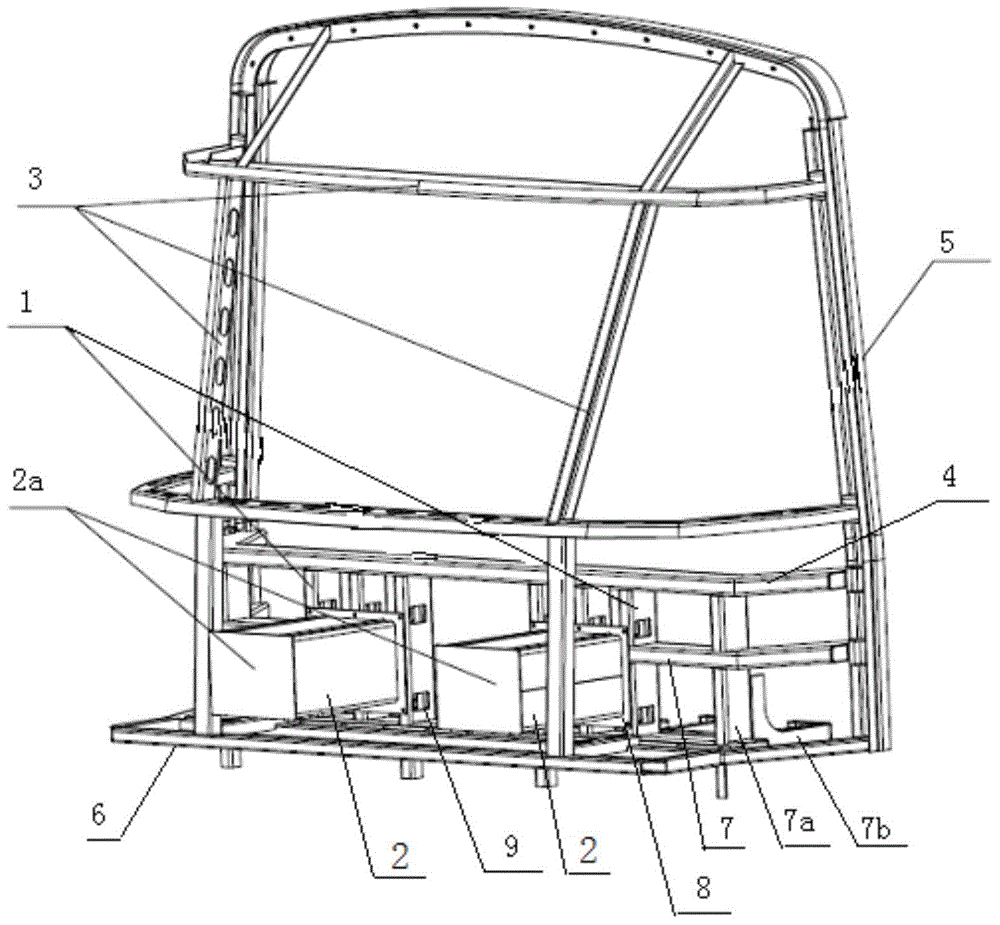
[0024] Such as figure 1 As shown, an energy-absorbing structure for a rail vehicle driver's cab includes a stop column 1, an energy-absorbing component 2, and a front-end frame 3 of the driver's cab. A console stop beam 4 is added under the front panel of the console, and the stop post 1 is vertically fixed between the console stop beam 4 and the underframe 6 .

[0025] The length of the energy-absorbing part 2 is at least 600mm, which can make it and the coupler together absorb the impact energy at a speed of 36km / h. The energy-absorbing component 2 adopts a square collision tube, and an anti-collision plate 2a is set at one end of the square collision tube, and a mounting seat 8 is set at the other end, and the middle is filled with aluminum honeycomb as an energy-absorbing material, and the mounting seat 8 fixes the energy-absorbing componen...


PUM

PropertyMeasurementUnit
Lengthaaaaaaaaaa

Abstract

The invention relates to an energy absorption structure for a railway vehicle cab. The energy absorption structure for the railway vehicle cab comprises energy absorption components, stopping pillars and cab front end frameworks. The stopping pillars are fixed on structural members of the cab, the stopping pillars are arranged below a panel at the front end of a control board of the cab, and the energy absorption components are fixed on the stopping pillars. The length of each energy absorption component is at least 600 mm. According to the energy absorption structure for the railway vehicle cab, due to the arrangement of the energy absorption components with large energy absorption capacity, the energy absorption structure and a vehicle coupler can bear the impact velocity of 36 km / h together; meanwhile, the stopping pillars are arranged so that the structure can be strengthened, and the backward diffusion caused by impact deformation is prevented; in addition, the rigidity of the cab front end frameworks is weakened, the energy absorption structure can participate in the deformation energy absorption process during impact, and thus the deformation energy absorption capacity of the energy absorption structure is effectively improved.

Description

technical field [0001] The invention relates to an energy-absorbing structure for a rail vehicle driver's cab, in particular to an energy-absorbing structure for a rail vehicle driver's cab that can increase the total amount of energy absorbed during impact. Background technique [0002] With the development of our country's social economy and the acceleration of people's life rhythm, the status of rail transit in urban traffic is getting higher and higher, and people's requirements for the safety and economy of rail vehicles are also getting higher and higher. The European Union has specially formulated "EN15227 Railway Application-Requirements for Crash Resistance of Railway Vehicle Body", which stipulates that the structure of rail vehicles should be designed reasonably. Sufficient escape space, CI level crash requirements in standard EN15227 stipulates that railway vehicles should be able to withstand impact speeds up to 36km / h. The existing coupler buffer device and pr...

Claims


Application Information

Patent Timeline
IPC IPC(8): B61D17/00B61C17/04
CPCB61D17/00B61F19/04
Inventor 田洪雷刘龙玺何燕华田爱琴丁叁叁马云双梁建英
Owner CRRC QINGDAO SIFANG CO LTD
Learn More