Anti-collision damping device for reversing

A shock absorbing device and anti-collision technology, which is applied to vehicle components, transportation and packaging, and vehicle safety arrangements, can solve problems such as immobility, easy torsional deformation of the girder, and deformation of the girder, so as to prolong the service life and reduce hard damage. Effect

Inactive Publication Date: 2016-12-07
HENAN VOCATIONAL & TECHN COLLEGE OF COMM
View PDF7 Cites 0 Cited by
  • Summary
  • Abstract
  • Description
  • Claims
  • Application Information

AI Technical Summary

Problems solved by technology

[0002] As is well known, along with the speeding up of expressway construction, it has greatly facilitated the travel of people and the transportation of goods, and medium-sized delivery vehicles are a kind of main type with great usage. The load-bearing part is all connected by the girder, that is, the girder is the assembly base of the medium-sized carrier vehicle, and bears various loads. In some cases, the bending or torsional deformation of the girder may occur, and the deformation of the girder will cause each assembly. Changes in the assembly and connection positions between the vehicles lead to failures in various systems, that is, when the vehicle is moving, parked or subjected to impact from the rear, the beam will be deformed, especially when the beam is twisted and deformed; furthermore, at present The rear part of the medium-sized transport vehicle adopts an anti-collision frame with a fixed structure integrated with the main beam. When reversing or being impacted by a rear-end vehicle, not only the main beam is easy to twist and deform, but also because the rear-end car gets in because the body is low. People on the car are more injured. Through the analysis of the current accidents, the car getting into the truck is the main cause of death for the driver and passengers of the car.

Method used


Image

  • Anti-collision damping device for reversing
  • Anti-collision damping device for reversing
  • Anti-collision damping device for reversing

Examples


Embodiment Construction

[0021] The present invention is further described below in conjunction with embodiment; The following embodiment is not for the limitation of the present invention, only as the mode of supporting the realization of the present invention, any equivalent structural replacement within the technical framework disclosed in the present invention, all is the present invention. the scope of protection of the invention;

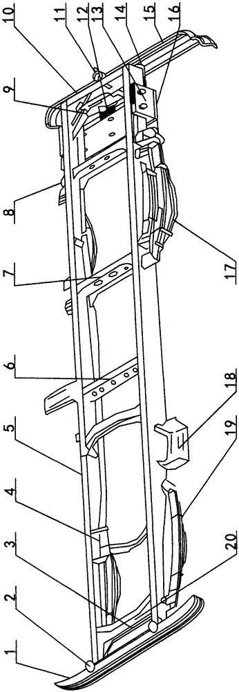
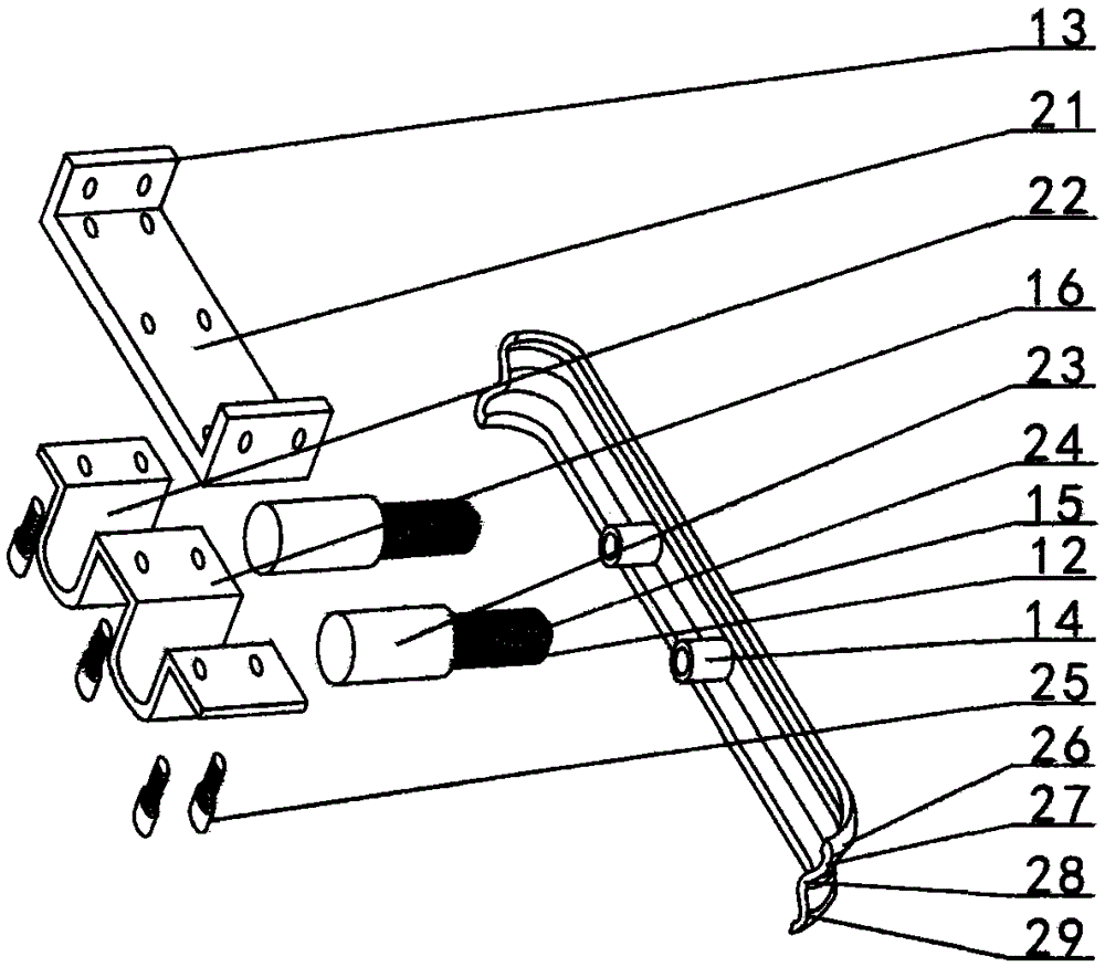
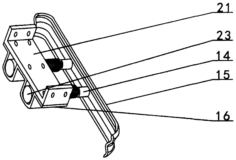
[0022] combined with figure 1 , 2 Or the reversing anti-collision damping device described in 3, comprises the crossbeam of medium-sized carrying vehicle, connecting plate 21, hydraulic cylinder fixed plate 16, hydraulic cylinder 23 and anti-collision damping plate 15; The crossbeam of described medium-sized carrying vehicle comprises longitudinal The beam 5, the crossbeam and the front bumper 1 are provided with a battery bracket 18 on one side of the front part of the two longitudinal beams 5, and a front crossbeam 20, Rear beam 10, at least two middle front beams...


PUM


Abstract

The invention provides a reversing anti-collision shock reduction device, and relates to a rear anti-collision device of a medium carrier vehicle. A plurality of beams are arranged between two longitudinal girders (5) from front to rear to form a crossbeam of the medium carrier vehicle. A connection plate (21) is fixedly connected with the rear portions of the two longitudinal girders (5). At least two hydraulic cylinders (23) are fixed to the lower portion of the connection plate (21) through a hydraulic cylinder fixing plate (16). Pistons (24) of the at least two hydraulic cylinders (23) are fixedly connected with an anti-collision shock reduction plate (15) on the rear portion to form the reversing anti-collision shock reduction device. According to the reversing anti-collision shock reduction device, the anti-collision shock reduction plate is arranged on the lower portion of the rear end of the crossbeam of the medium carrier vehicle and is protected by the hydraulic cylinders and a spring, the harm, caused by vehicle collision, to the crossbeam can be partially defused, and the situation that a car is plunged in the bottom of a truck and the driver of the car and passengers are dead can be reduced.

Description

【Technical field】 [0001] The invention relates to a rear anti-collision device of a medium-sized carrier vehicle, in particular to a shock-absorbing device when the carrier vehicle is reversed and collided, or self-collision-proof when being rear-ended, and a shock-absorbing device for reducing casualties of a rear-end vehicle. 【Background technique】 [0002] As is well known, along with the speeding up of expressway construction, it has greatly facilitated the travel of people and the transportation of goods, and medium-sized delivery vehicles are a kind of main type with great usage. The load-bearing part is all connected by the girder, that is, the girder is the assembly base of the medium-sized carrier vehicle, and bears various loads. In some cases, the bending or torsional deformation of the girder may occur, and the deformation of the girder will cause each assembly. Changes in the assembly and connection positions between the vehicles lead to failures in various syst...

Claims


Application Information

Patent Timeline
Patent Type & Authority Patents(China)
IPC IPC(8): B60R19/56B62D21/15
CPCB60R19/56B62D21/152
Inventor 齐伟袁荷伟吴笑伟张秀如贾东明朱学军宋阳
Owner HENAN VOCATIONAL & TECHN COLLEGE OF COMM
Why Eureka
Try Eureka