Method and clamp for eliminating deformation of blade caused by machining stress

A technology for processing stress and blades, applied in the direction of manufacturing tools, metal processing equipment, metal processing machinery parts, etc., can solve problems such as blade deformation, and achieve the effect of reducing stress deformation, improving processing efficiency, and eliminating deformation.

Inactive Publication Date: 2015-03-25
SHENYANG LIMING AERO-ENGINE GROUP CORPORATION
View PDF10 Cites 3 Cited by
  • Summary
  • Abstract
  • Description
  • Claims
  • Application Information

AI Technical Summary

Problems solved by technology

[0004] A clamping method that eliminates blade deformation due to processing stress. The clamping tooling of the positioning shaft of the clamp is designed as a hydraulic centering clamp. According to the adjustable clamping force of the hydraulic clamp, the critical torque of blade deformation is measured. , adjust the clamping force torque of the hydraulic centering fixture to be lower than the critical torque value of the deformation of the blade. Less than the deformation torque, the positioning part of the fixture is slightly twisted or extended with the deformation direction of the part. After the part releases the stress, the hydraulic centering fixture clamps the clamping positioning part again to continue processing, thus solving the problem of deformation of the blade due to processing stress

Method used


Image

  • Method and clamp for eliminating deformation of blade caused by machining stress

Examples


Embodiment Construction

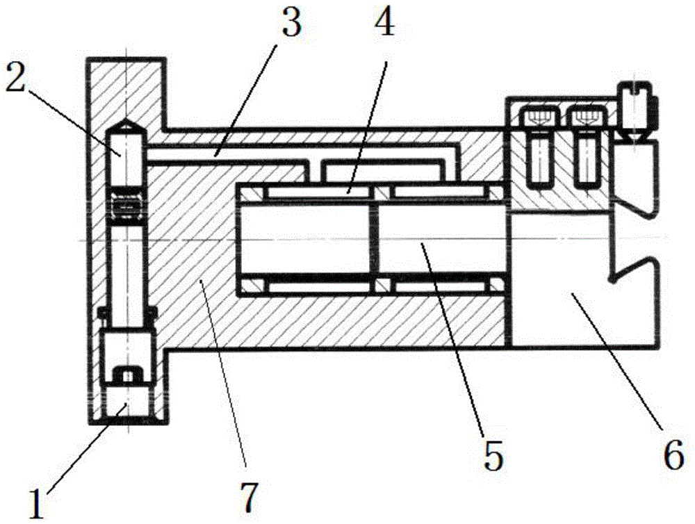
[0008] The present invention is specifically described below in conjunction with accompanying drawing, as figure 1 As shown, the fixture of the present invention includes a hydraulic centering fixture 7, and the hydraulic centering fixture 7 is provided with a cavity one 4, a cavity two 3, and a cavity three 2, and the positioning shaft 5 of the fixture is arranged in the cavity one 4 Inside, the cavity one 4, the cavity two 3, and the cavity three 2 are sequentially connected; the cavity three 2 is provided with an adjusting nut 1, and the adjusting nut 1 can move axially by using the thread on the wall of the cavity three 2; Cavity one 4, cavity two 3, cavity three 2 are filled with liquid plastics.

[0009] In the present invention, the clamping tooling of the positioning shaft of the clamp is designed as a hydraulic centering clamp, and according to the adjustable clamping force of the hydraulic clamp, the critical torque of blade deformation is measured, and the clamping ...


PUM


Abstract

The invention discloses a clamping method and clamp for eliminating deformation of blade caused by machining stress. A clamping tool of a locating shaft of the clamp is designed into a hydraulic centering clamp, the critical torque at which the blade deforms is measured according to the characteristic that the clamping force of the hydraulic clamp is adjustable, the torque of the clamping force of the hydraulic centering clamp is adjusted to be lower than the critical torque value at which the blade deforms, when the deformation torque generated by an element is larger than critical torque value, the clamp is not subjected to rigid restrained deformation, instead, the locating part of the clamp twists or extends slightly in the deforming direction of the element due to the fact that the clamping torque is smaller than the deformation torque, after the element releases stress, the hydraulic centering clamp clamps the clamping locating part again for continuous machining, and therefore the problem that the blade deforms due to the machining stress is solved. The clamping method and clamp have the advantages that by means of the clamping method and clamp, deformation generated by the element of the blade in machining can be eliminated; the clamping method and clamp can be used for machining various types of blades, reduce waste products caused by stress deformation in machining of the blades and improve machining efficiency by over 300%.

Description

Technical field: [0001] The invention relates to a fixture, in particular to a fixture used in CNC milling of airfoil profiles of aeroengine blades, or in the processing of similar structural parts. technical background: [0002] The structure of aero-engine blade parts is complex. The airfoil shape is divided into blade basin and blade back, which are respectively connected by circular arcs with different radii to form the intake side and exhaust side. The shape and surface structure of the blade body is complex. Evenly distributed irregular curved surface, and the minimum section thickness is only about 1mm, it is very easy to deform due to uneven stress caused by processing, and the blade is scrapped due to deformation. Contents of the invention [0003] In order to solve the above-mentioned technical problems, the object of the present invention is to provide a clamping method that eliminates the deformation of the blade due to processing stress. The specific technical...

Claims


Application Information

Patent Timeline
Patent Type & Authority Applications(China)
IPC IPC(8): B23Q3/00
CPCB23Q3/063B23Q3/082
Inventor 孟书威
Owner SHENYANG LIMING AERO-ENGINE GROUP CORPORATION
Why Eureka
Try Eureka