
Installation device for engine valve spring upper gasket and lock clamp

An engine valve and installation device technology, applied in assembly machines, metal processing, metal processing equipment, etc., can solve problems such as affecting assembly efficiency, blocking oil filters, and scrapping engine cylinder blocks, and achieves easy and simple assembly and disassembly work. , The effect of saving time and cost and reducing the difficulty of work

Active Publication Date: 2015-03-25
ANHUI JIANGHUAI AUTOMOBILE GRP CORP LTD
View PDF8 Cites 4 Cited by
  • Summary
  • Abstract
  • Description
  • Claims
  • Application Information

AI Technical Summary

Problems solved by technology

[0003] Install the gasket and lock clip on the valve spring according to the above-mentioned traditional method. Due to the valve inclination angle of some engine cylinders, the assembly tools are rough, which will easily lead to laborious assembly and seriously affect the assembly efficiency.
Using the above method to remove the gasket and lock clip on the valve spring is very likely to cause structural damage to the valve spring and the gasket on the valve spring, and more seriously may damage the valve sealing structure of the engine block, resulting in the scrapping of the engine block
In addition, if the valve spring upper gasket and lock clip are removed from the whole machine by the above method, under the impact force, the lock clip will fall off and splash, and it is likely to fall into the oil pan
If it is not detected and dealt with in time, and the engine is assembled to the vehicle and then ignited and started, since the lock clip is still in the oil pan, it is very likely that random oil will enter the lubrication system, thereby clogging the oil filter, and even causing more serious consequences

Method used


Image

  • Installation device for engine valve spring upper gasket and lock clamp
  • Installation device for engine valve spring upper gasket and lock clamp
  • Installation device for engine valve spring upper gasket and lock clamp

Examples


Embodiment Construction

[0041] Below in conjunction with accompanying drawing and specific embodiment the present invention is described in further detail:

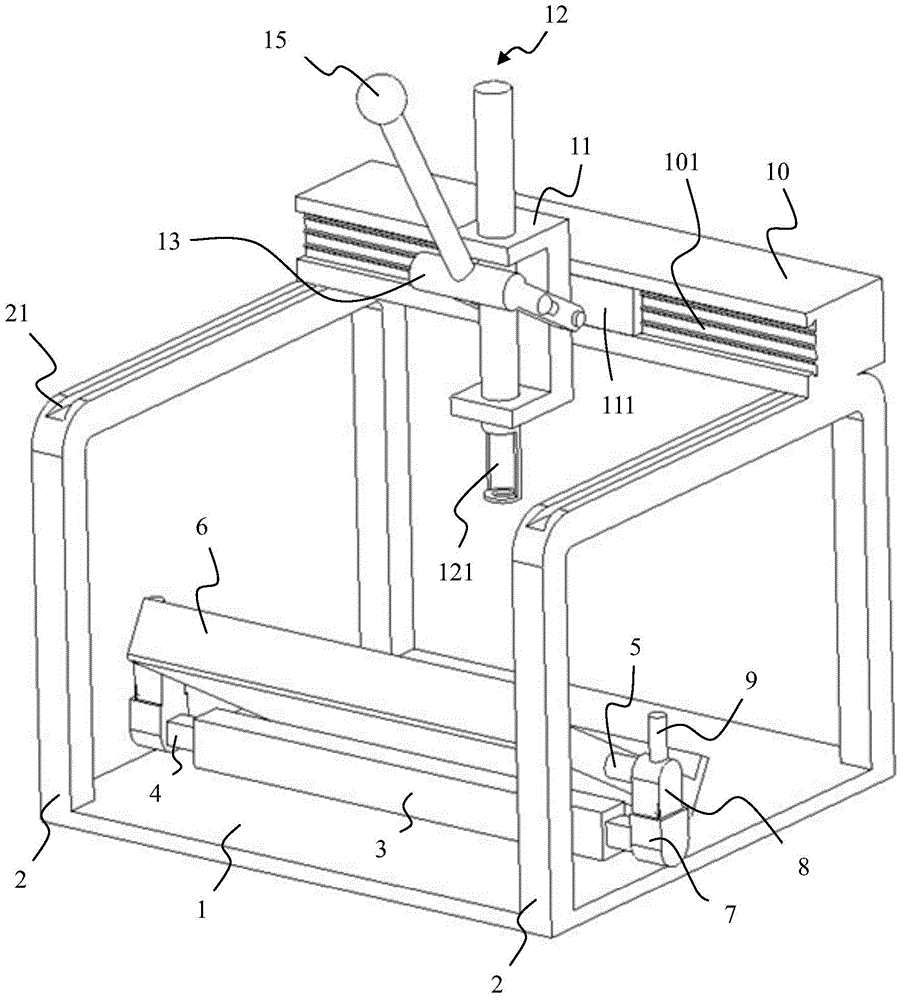
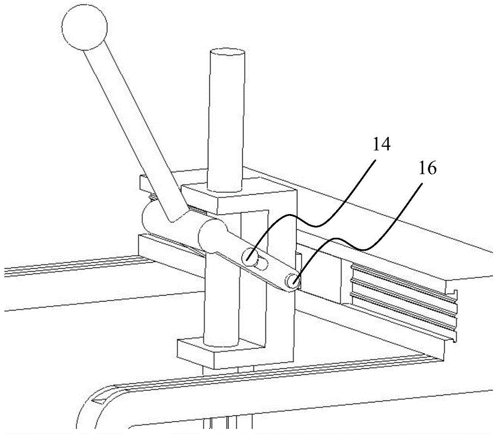
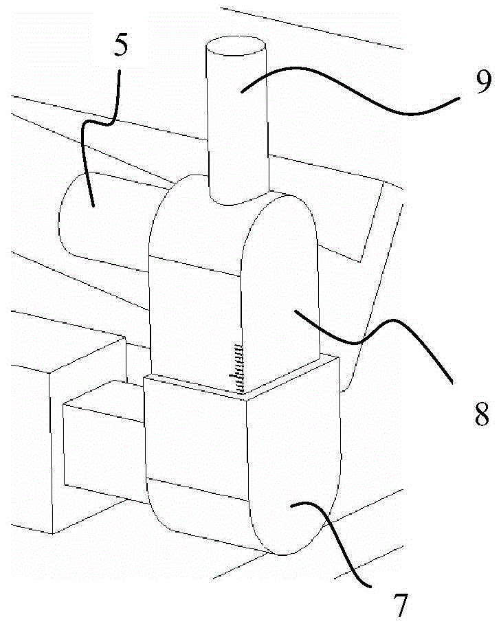
[0042] An installation device for gaskets and lock clips on engine valve springs, comprising: a main frame, a cylinder head placing part and a pressing part. The cylinder head placing part is arranged in the lower part of the main frame in a movable manner, and is used for placing the cylinder head to be assembled; Clamping and pressing into the cylinder head to be assembled; the angle of the pressing direction of the cylinder head placing part relative to the pressing part can be adjusted.

[0043] The specific structure is as follows:

[0044] Such as figure 1 and Figure 4 As shown, the main frame includes a bottom plate 1 and a frame 2. Both sides of the bottom plate 1 are provided with a box 2, and the top of the box 2 is provided with a chute 21, the press-fitting part is arranged on the top of the box 2 and can slide along the chute 2...


PUM


Abstract

The invention discloses an installation device for an engine valve spring upper gasket and a lock clamp. A cylinder cover is placed on a cylinder cover placement portion. The valve spring upper gasket and the lock clamp are installed at the to-be-installed portions of the cylinder cover in a press-fitting mode through a press-fitting portion. The defect that according to a traditional installation mode, one cylinder cover needs a tool special for a valve spring upper gasket and a lock clamp is overcome. Labor waste and time waste are reduced. The cylinder cover placement portion has the adjustable angle relative to the press-fitting direction of the press-fitting portion, so that the cylinder cover is adjusted to be at any angle, and the universality of the installation device is improved. In the using process, the thought that the dip angle of a cylinder cover valve is compensated for is adopted, and the assembly of the valve spring upper gasket and the lock clamp is changed into the normal assembly relationship, so that assembly and disassembly become easier, the working difficulty is greatly lowered, and the time cost is saved.

Description

technical field [0001] The invention belongs to the field of engine assembly equipment, in particular to an installation device for gaskets and lock clips on engine valve springs. Background technique [0002] The installation of the gasket and lock clip on the engine valve spring is usually carried out by manual assembly. During assembly, two operators cooperate with each other, one of them presses down the valve spring with a hollow mandrel slotted on one side, and the other quickly installs the gasket and lock clip on the valve spring in place, releases the mandrel, and the spring Return, thereby compressing the washer on the spring and the locking clip. Due to the lack of special tools during disassembly, violent disassembly is generally used, that is, one end of the mandrel is used to press the gasket on the spring, and then the other end of the mandrel is hit with a rubber hammer. Under the great impact force, the lock clip falls off, relying on The gasket on the val...

Claims


Application Information

Patent Timeline
IPC IPC(8): B23P21/00
CPCB23P19/006B23P19/02B23P19/027
Inventor 王森刘凯张宝平
Owner ANHUI JIANGHUAI AUTOMOBILE GRP CORP LTD
Learn More