
Pressure-coupled chromatography column fluid distributor

A technology of fluid distributor and chromatographic column, which is applied in the field of chromatographic column, can solve the problems of affecting chromatographic efficiency, large pressure loss, large length difference, etc., achieve uniform flow distribution, improve chromatographic efficiency, and be easy to implement Effect

Inactive Publication Date: 2017-10-27
YUANCHUANG JINGKE BIOTECH CHANGSHA CO LTD
View PDF9 Cites 0 Cited by
  • Summary
  • Abstract
  • Description
  • Claims
  • Application Information

AI Technical Summary

Problems solved by technology

like Figure 8 As shown, the traditional chromatographic column fluid distribution plate has a radial flow groove on one side, and a liquid inlet or outlet in the center. The fluid enters from the liquid inlet, flows through the radial flow groove to the edge of the fluid distribution plate, and then The gel flows out to the edge of another fluid distribution plate, and then flows through the flow channel of another fluid distribution plate to its central liquid outlet, or directly flows through the gel to another fluid from the central liquid inlet of a fluid distribution plate The liquid outlet in the center of the distribution plate flows out, causing the fluid to pass through different paths from the liquid inlet to the liquid outlet. The flow rate of the fluid per unit area of ​​the gel is quite different, which makes the flow distribution of the fluid in the gel uneven, thus affecting the chromatography efficiency

Method used


Image

  • Pressure-coupled chromatography column fluid distributor
  • Pressure-coupled chromatography column fluid distributor
  • Pressure-coupled chromatography column fluid distributor

Examples


Embodiment Construction

[0018] The following examples are further explanations and illustrations of the present invention, and do not constitute any limitation to the present invention.

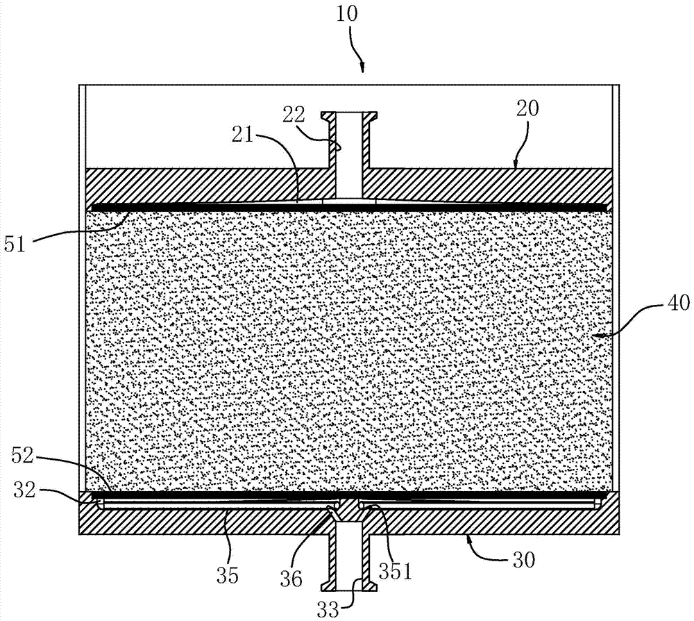
[0019] refer to figure 1 , the pressure-coupled chromatography column fluid distributor of the present invention includes a first distribution plate 20 and a second distribution plate 30 . The first distribution plate 20 and the second distribution plate 30 are respectively arranged at the two ends of the gel 40 in the chromatography column 10. The gel 40 can be a gel known in the art, which is used for different components in the liquid separation.

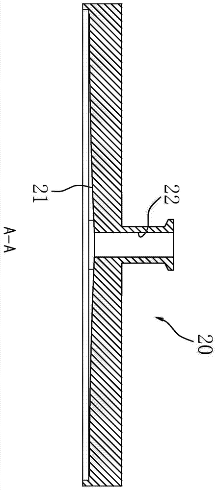
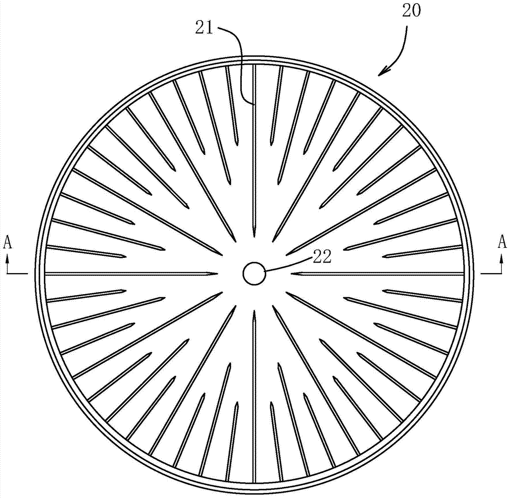
[0020] Such as figure 2 , image 3 As shown, the first distribution plate 20 is a disc-shaped body made of polypropylene plastic, and a plurality of radial first fluid grooves 21 are provided on the surface of the side opposite to the gel. In this embodiment, the first A fluid groove 21 is arranged on the lower side of the first distribution plate 20, and a plura...


PUM


Abstract

A pressure coupling type chromatographic column fluid distributor. The fluid distributor comprises a first distribution plate (20) and a second distribution plate (30). The first distribution plate (20) and the second distribution plate (30) are respectively disposed on two ends of a separation purpose gel (40) in a chromatographic column (10). Multiple radial first fluid grooves (21) are distributed in a spaced manner along the circumference of a side surface, opposite to the gel (40), of the first distribution plate (20). A first screen mesh (51) is disposed on the outer side of the corresponding first fluid groove (21). A fluid outlet / inlet (22) in communication with the corresponding first fluid groove (21) is disposed at the center of the first distribution plate (20). Multiple radial second fluid grooves (31) are distributed in a spaced manner along the circumference of a side surface, opposite to the gel (40), of the second distribution plate (30). A second screen mesh (52) is disposed on the outer side of the corresponding second fluid groove (31). An annular flow groove (32) is formed between the edge of the second distribution plate (30) and the tail end of the corresponding second fluid groove (31). A fluid inlet / outlet (33) is disposed at the center of the second distribution plate. Multiple radial flow channels (34) for connecting the annular flow grooves (32) and the fluid inlet / outlet (33) are evenly distributed in the side surface, opposite to the gel, of the second distribution plate.

Description

【Technical field】 [0001] The invention relates to a chromatographic column in gel chromatography technology, in particular to a pressure-coupled chromatographic column fluid distributor. 【Background technique】 [0002] Chromatography is a gel separation method, typically silica gel chromatography. It is separated by reacting the separation fluid with the gel in the chromatographic column through molecular sieve, ion exchange, etc. Chromatographic column is the main body of gel chromatography technology, generally using glass tube or plexiglass tube, which is filled with gel, and equipped with fluid distribution plate and sieve plate at both ends. Such as Figure 8 As shown, the traditional chromatographic column fluid distribution plate has a radial flow groove on one side, and a liquid inlet or outlet in the center. The fluid enters from the liquid inlet, flows through the radial flow groove to the edge of the fluid distribution plate, and then The gel flows out to the ed...

Claims


Application Information

Patent Timeline
Patent Type & Authority Patents(China)
IPC IPC(8): B01D15/14
CPCB01D15/14G01N30/60
Inventor 肖宇圻
Owner YUANCHUANG JINGKE BIOTECH CHANGSHA CO LTD
Learn More