
Self-similarity micro-channel heat sink with jet flow structure

A microchannel and self-similar technology, applied in electrical components, electrical solid devices, circuits, etc., can solve problems such as uneven flow distribution and uneven heat transfer restrictions

Active Publication Date: 2018-11-13
SICHUAN UNIV
View PDF4 Cites 10 Cited by
  • Summary
  • Abstract
  • Description
  • Claims
  • Application Information

AI Technical Summary

Problems solved by technology

The uneven flow distribution inside the self-similar microchannel heat sink and the resulting uneven heat transfer greatly limit its application and promotion, and related problems need to be solved urgently

Method used


Image

  • Self-similarity micro-channel heat sink with jet flow structure
  • Self-similarity micro-channel heat sink with jet flow structure
  • Self-similarity micro-channel heat sink with jet flow structure

Examples


Embodiment Construction

[0017] The main content of the present invention is further illustrated below in conjunction with specific examples, but the content of the present invention is not limited to the following examples.

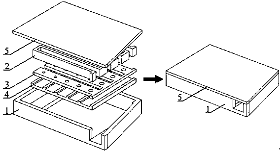
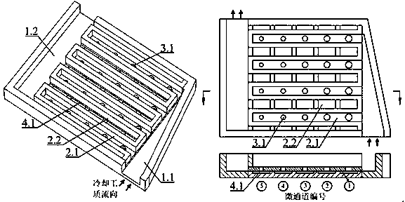
[0018] The invention discloses a self-similar microchannel heat sink with a jet hole structure, which comprises a main inflow and outflow structure (1), a split layer (2), a jet hole plate layer (3), a microchannel layer (4), and top cover (5). The inflow and outflow structure (1) includes a main inflow channel (1.1) and a main outflow channel (1.2). The split layer (2) includes split sub-channels (2.1) and outflow sub-channels (2.3). The jet orifice plate layer (3) is provided with a number of jet holes (3.1), and the opened positions are arranged along the flow direction of the sub-channels (2.1), and the diameter of each jet hole decreases along the flow. The microchannel layer (4) is located below the jet orifice layer (3), and is composed of several microgrooves arranged ...


PUM


Abstract

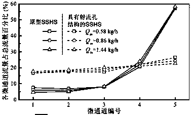
The invention discloses a self-similarity micro-channel heat sink with a jet flow structure. The heat sink comprises a main inflow and outflow structure, a shunt layer, a jet flow pore plate layer, amicro-channel (overflow channel) layer and a top cover plate. A plurality of jet flow holes are formed in the jet flow pore plate layer below the shunt layer, and the forming positions are arranged along the flowing directions of shunt sub-channels. A sub-channel layer is positioned below the jet flow pore plate layer and is composed of a plurality of microgrooves arranged in parallel, and the intermittent micro-channel (overflow channel) structure is formed by the microgrooves and the bottom surface of the jet flow pore plate layer. A main inflow channel adopts a cross section reduced structure to guarantee uniform distribution of a cooling working medium towards the shunt sub-channels. The diameters of jet flow holes in the jet flow pore plate below the shunt layer are reduced along theflow, so that the micro-channels (overflow channels) below the shunt sub-channels obtain similar flow, and the uniformity of heat exchange is improved. The cooling working medium vertically impacts the bottom surfaces of the overflow channels after passing through the jet flow holes, a certain jet flow impact effect is formed, and heat transfer enhancement is achieved.

Description

technical field [0001] The invention relates to a high-performance heat sink, which is suitable for cooling high heat generation and compact equipment such as high heat release electronic chips, high-power laser diodes, and concentrating solar cells. It is a self-similar microchannel heat sink with a jet structure. Shen. Background technique [0002] Many miniaturized and high-heating devices, such as high-performance electronic chips, high-power laser diodes, concentrating solar cells, etc., will generate strong heat release during operation (even exceeding 100W / cm 2 ), which poses a challenge to the heat dissipation capability of the heat sink. In order to effectively cool these devices and ensure their safe and reliable operation, related heat dissipation technologies and equipment have always been research hotspots. [0003] The liquid-cooled microchannel heat sink has a stronger heat transfer capacity than the traditional air-cooled conventional design heat sink, and i...

Claims


Application Information

Patent Timeline
Patent Type & Authority Applications(China)
IPC IPC(8): H01L23/367H01L23/473
CPCH01L23/367H01L23/473
Inventor 唐巍孙立成杜敏唐继国莫政宇
Owner SICHUAN UNIV
Learn More