Electricity discharging unit and air cleaning device using same
A technology of air purification device and discharge unit, which is applied to electrical components, chemical/physical/physical-chemical processes of applying energy, and applications, etc., and can solve the problems that the amount of ions released is not easy to increase, and the ions are not effectively diffused.
- Summary
- Abstract
- Description
- Claims
- Application Information
AI Technical Summary
Problems solved by technology
Method used
Image

Examples
Embodiment approach 1
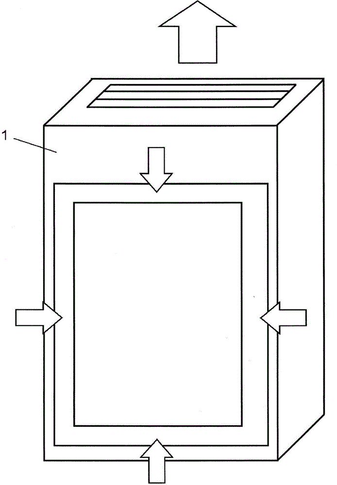
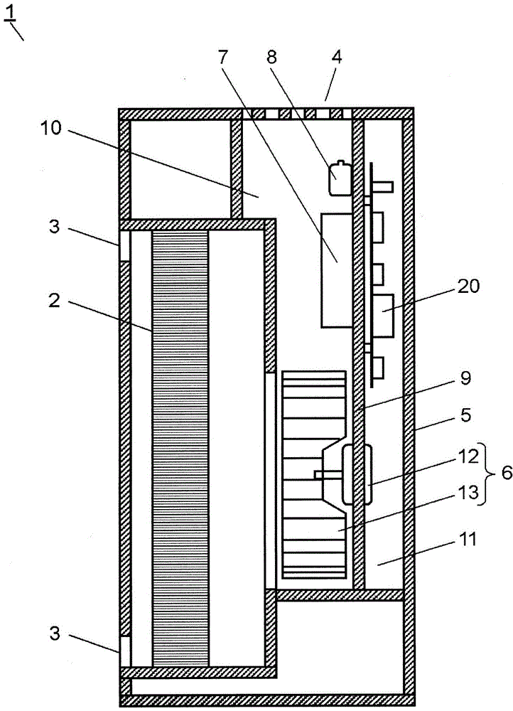
[0031] figure 1 It is a perspective view of the air cleaner according to Embodiment 1 of the present invention, figure 2 is a sectional view of the air cleaning device. Such as figure 1 , figure 2 As shown, the air cleaning device 1 having a substantially elongated box shape sucks indoor air from four front sides, and passes through an air filter 2 to convert the air into purified air. Furthermore, the air cleaning device 1 blows the ions generated by the discharge unit 7 and the active species generated by the electrostatic atomization unit 8 together with purified air from the ceiling to the room.
[0032] The air cleaner 1 includes a main body 5 having an intake port 3 and an exhaust port 4 , an air blower 6 inside the main body 5 , a discharge unit 7 , and an electrostatic atomization unit 8 . The main body 5 is divided into a ventilation path portion 10 communicating with the intake port 3 and the exhaust port 4 and a space portion 11 by a partition plate portion 9 ...
Embodiment approach 2
[0106] In Embodiment 2 of the present invention, only differences from Embodiment 1 will be described, and the same components as in Embodiment 1 will be assigned the same reference numerals, and detailed description thereof will be omitted.
[0107] Figure 11A is an external perspective view of a discharge cell according to Embodiment 2 of the present invention, Figure 11B is the discharge circuit diagram of the discharge unit. Such as Figure 11A As shown, the discharge unit 7 is configured to include a discharge unit 7 a, a first high voltage generating unit 26 forming the power supply unit 20 , and a resistor 63 .
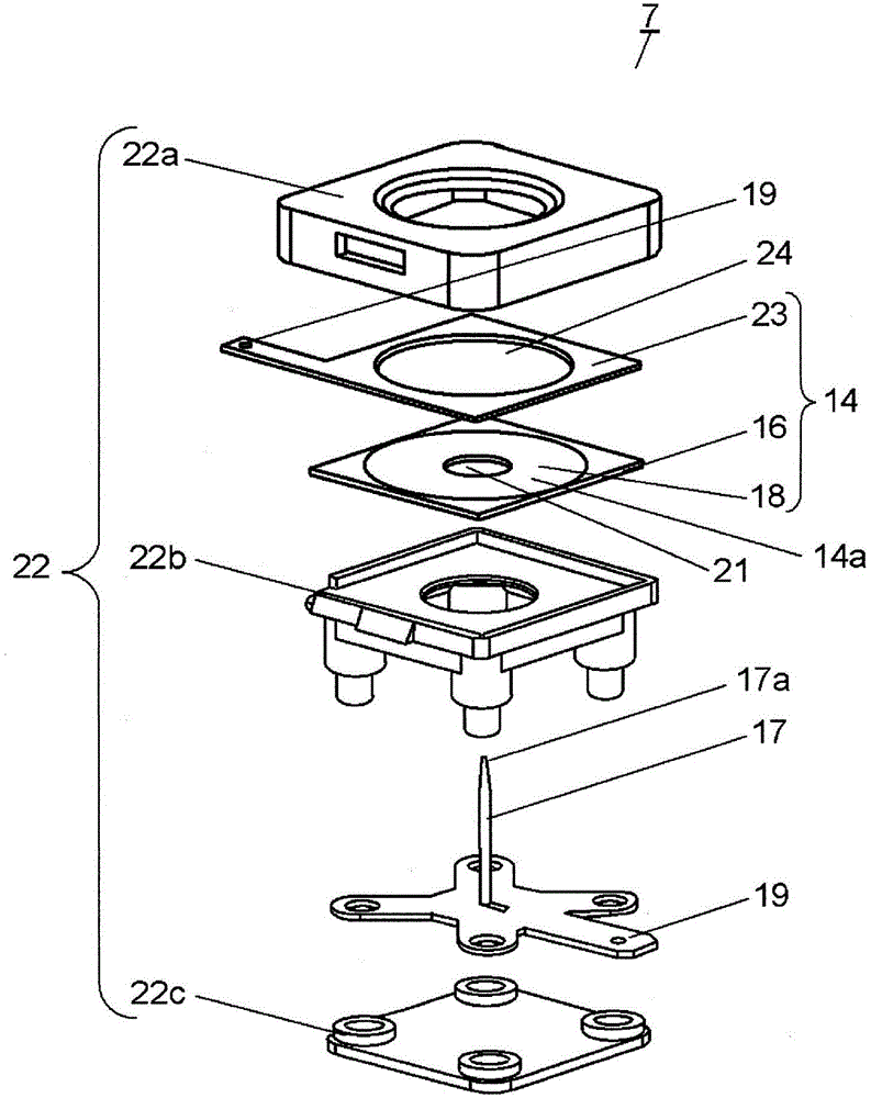
[0108] Figure 12 It is an exploded perspective view of the discharge portion of the discharge cell according to Embodiment 2 of the present invention. Such as Figure 12 As shown, the discharge part 7a is formed by the 1st counter electrode 14, the needle-shaped 1st discharge electrode 17, and the support member 22. As shown in FIG. Here, the first cou...
Embodiment approach 3
[0148] In Embodiment 3 of the present invention, only differences from Embodiments 1 and 2 will be described, and the same reference numerals will be assigned to the same components as Embodiments 1 and 2, and detailed description thereof will be omitted. Figure 18A is a conceptual diagram showing a discharge state of a discharge cell according to Embodiment 3 of the present invention, Figure 18B It is an enlarged view of the first discharge electrode tip portion of the discharge cell.
[0149] like Figure 18A The orthogonal portion where the first discharge electrode 17 is perpendicular to the first counter electrode 14 is referred to as an orthogonal portion 17b, and the orthogonal portion 17b is covered with a heat-shrinkable tube 17c of an insulator. The heat-shrinkable tube 17c also covers a part of the inclination part 17d of the needle-shaped front-end|tip of the 1st discharge electrode 17. As shown in FIG. The heat-shrinkable tube 17c utilizes the shape memory eff...
PUM
 Abstract
Description
Claims
Application Information
 - R&D
- Intellectual Property
- Life Sciences
- Materials
- Tech Scout
- Unparalleled Data Quality
- Higher Quality Content
- 60% Fewer Hallucinations
Browse by: Latest US Patents, China's latest patents, Technical Efficacy Thesaurus, Application Domain, Technology Topic, Popular Technical Reports.
© 2025 PatSnap. All rights reserved.Legal|Privacy policy|Modern Slavery Act Transparency Statement|Sitemap|About US| Contact US: help@patsnap.com