
Optical coherent receiver time delay and phase difference test method and test system

A technology of coherent receiver and test method, which is applied in the field of optical communication, can solve the problems of incomplete demodulation, poor time delay, and inability to obtain high-performance receiving demodulation, achieve good repeatability, overcome phase difference and time delay , the effect of simple structure

Active Publication Date: 2015-03-18
SHANGHAI BRANCH FUZHOU GAOYI COMM CO LTD
View PDF6 Cites 14 Cited by
  • Summary
  • Abstract
  • Description
  • Claims
  • Application Information

AI Technical Summary

Problems solved by technology

After long-distance transmission, there is often a time delay difference between channels after the optical receiver receives and demodulates, making the demodulation incomplete, so that high-performance receiving and demodulating cannot be obtained

Method used


Image

  • Optical coherent receiver time delay and phase difference test method and test system
  • Optical coherent receiver time delay and phase difference test method and test system
  • Optical coherent receiver time delay and phase difference test method and test system

Examples


Embodiment Construction

[0029] The present invention will be further described below in conjunction with the accompanying drawings and specific embodiments.

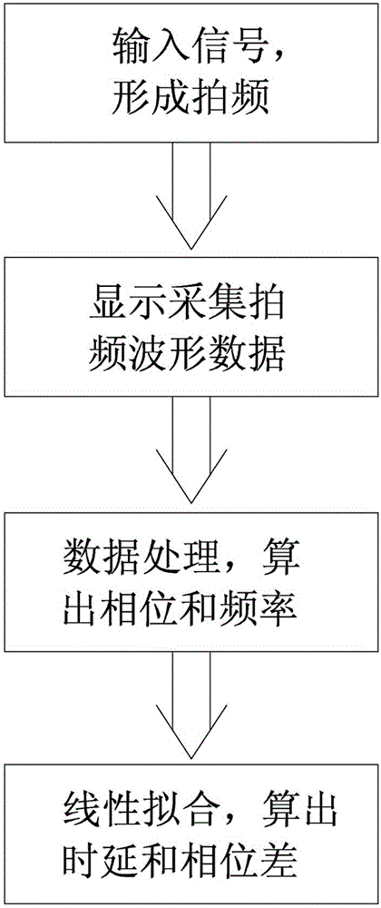
[0030] According to the superposition principle of waves, two simple harmonic waves with the same propagation direction and a small frequency difference will be superimposed to form a beat. Such as figure 1 As shown, the optical coherent receiver time delay and phase testing method of the present invention comprises the following steps:

[0031] a) By inputting scanning signal light with a frequency similar to that of the local oscillator signal to the optical coherent receiver to be tested, a series of beat frequencies are formed with the local oscillator signal;

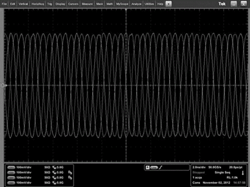
[0032] b) Use an oscilloscope to simultaneously connect any two radio frequency signal output channels of the optical coherent receiver to be tested, and detect and collect waveform data of all beat frequencies under each wavelength of the input scanning signal light;

[0033] c) ...


PUM


Abstract

The invention discloses an optical coherent receiver time delay and phase difference test method which comprises the following steps: generating beat frequency through inputting scanning signals, of which the frequency is similar to that of local oscillator signals, to an optical coherent receiver to be tested; collecting beat frequency information output by each radio frequency of the optical coherent receiver to be tested by utilizing an oscilloscope; carrying out noise elimination through the FFT operation and calculating the phase and frequency of the beat frequency; and finally, carrying out linear fitting to obtain relation curve of the phase and frequency, and calculating the time delay and phase difference between channels of the optical coherent receiver to be tested according to the curve. The invention also discloses a test system for the method. The test system comprises a local oscillator signal source, a tunable scanning signal source, the optical coherent receiver to be tested, the oscilloscope and a data processing unit. The beat frequency method is utilized to test the time delay and phase difference between the channels of the optical coherent receiver to be tested, so that simple and practicable effects are achieved, time delay and phase difference between the channels can be accurately measured, the difficulty that a conventional instrument cannot directly measure the phase difference and time delay between 25 GHz high-speed signal channels is overcome, and the repeatability of test data is good.

Description

technical field [0001] The invention relates to the field of optical communication, in particular to a method and system for testing time delay and phase difference of an optical coherent receiver. Background technique [0002] The development of communication technology has greatly promoted the progress of human society. From the second half of the 20th century to the present, optical fiber communication technology has developed rapidly at an unprecedented speed. With the development of the Internet, various emerging network traffic services have sprung up, including web page data, e-mail, online games, online videos, etc. The emergence and growth of these services have put forward new requirements for the capacity of communication systems. [0003] At the receiving end, the optical receiver receives and demodulates the optical signal modulated at the transmitting end. After long-distance transmission, there is often a delay difference between channels after receiving and ...

Claims


Application Information

Patent Timeline
Patent Type & Authority Applications(China)
IPC IPC(8): H04B10/079
Inventor 许祥益李伟启王向飞徐小伟邱云萍
Owner SHANGHAI BRANCH FUZHOU GAOYI COMM CO LTD
Learn More