Inductor and switching circuit comprising inductor
A switching circuit and inductor technology, applied in the field of inductors and switching circuits containing them, can solve the problems of increased cost, low magnetic permeability magnetic core materials, etc., and achieve the effect of reducing eddy current loss and reducing costs.
- Summary
- Abstract
- Description
- Claims
- Application Information
AI Technical Summary
Problems solved by technology
Method used
Image


Examples
Embodiment 1
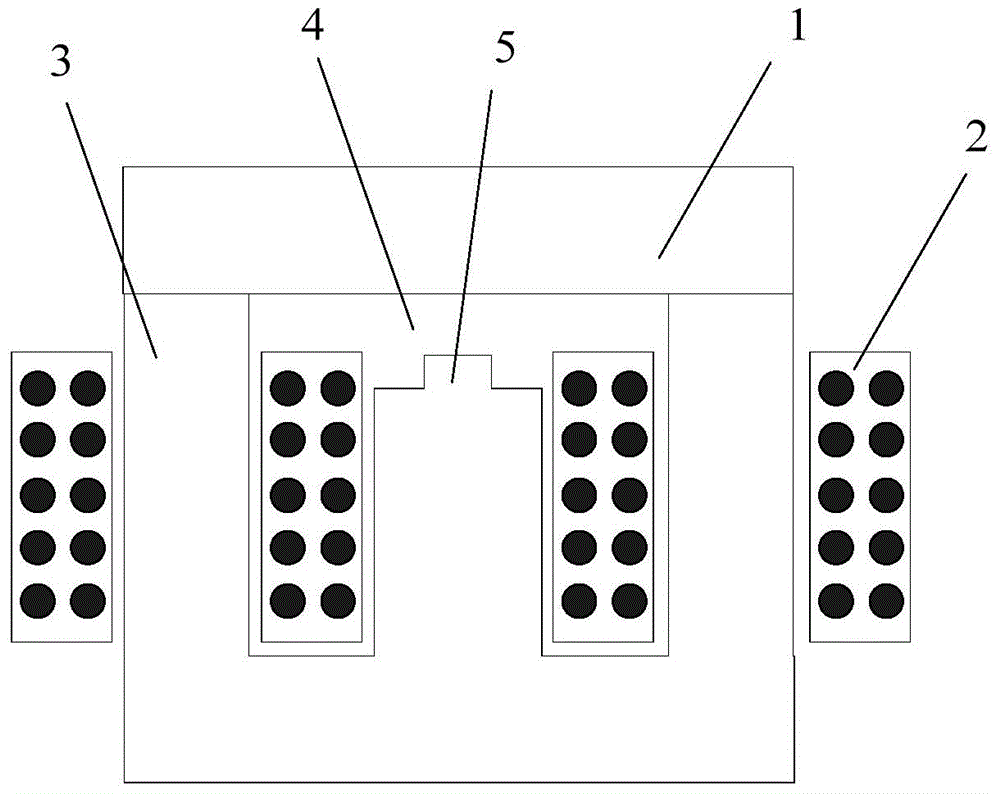
[0042] This embodiment provides an inductor, the schematic side view of the inductor structure is as follows Figure 5 shown. The inductor has a UI structure, including a magnetic core structure composed of a yoke 101 and a stem 103 , and the yoke 101 and the stem 103 form a closed magnetic circuit. The stem is the part of the magnetic core wrapped by the winding, and the yoke is the part of the magnetic core not wrapped by the winding, which is also the case in the following embodiments.
[0043] The coil winding 102 is disposed around the stem 103 , and between the stem 103 and the yoke 101 includes an insulating plate 104 near the yoke and a planar magnetic core unit 105 near the stem 103 .
[0044] The material of the stem 103 and the yoke 101 is a material with high magnetic permeability and high saturation magnetic induction, which can be silicon steel sheet, amorphous, nanocrystalline, etc., and its relative magnetic permeability is greater than or equal to 500. The m...
Embodiment 2
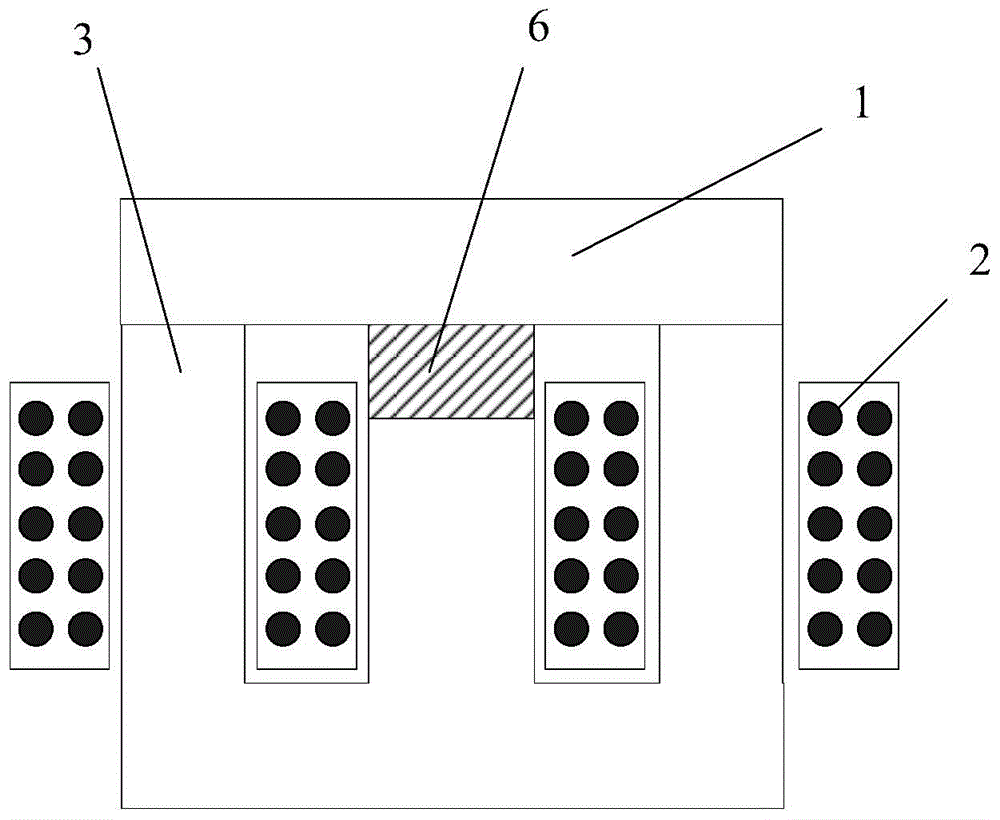
[0076] This embodiment provides another inductance structure, the schematic side view of the inductance structure is as follows Figure 10 shown.
[0077] The inductor has a UI structure, including a magnetic core structure formed by a yoke 201 and a stem 203 , and the yoke 201 and the stem 203 form a closed magnetic circuit. The coil winding 202 is disposed around the stem 203 , and between the stem 203 and the yoke 201 includes an insulating plate 204 near the yoke and a planar magnetic core unit 205 near the stem 203 .
[0078] The material of the magnetic core composed of the stem 203 and the yoke 201 is a material with high magnetic permeability and high saturation magnetic induction, which can be silicon steel sheet, amorphous, nanocrystalline, etc., and its relative magnetic permeability is greater than or equal to 500. The material of the planar magnetic core unit 205 is a material with high magnetic permeability and low saturation magnetic induction, which can be man...
Embodiment 3
[0087] This embodiment provides another inductance structure, the schematic side view of the inductance structure is as follows Figure 13 shown.
[0088] The inductor is a three-phase five-column structure, including a magnetic core structure composed of at least one yoke and a core. The at least one yoke and the core form a closed magnetic circuit. The at least one yoke includes an upper yoke 301, a lower The yoke 301-1 and the side yoke 301-2.
[0089] The coil winding 302 is arranged around the stem 303, and between the stem 303 and the upper yoke 301 and the lower yoke 301-1 includes an insulating plate 304 near the yoke and a planar magnetic core unit 305 near the stem 303. The magnetic core structure of the embodiment includes three stems, and the stem 303 is one of the stems. There is a planar magnetic core unit 305 between the upper end of each stem and the upper yoke, and there is a planar magnetic core unit 305 between the lower end of each stem and the lower yoke...
PUM
| Property | Measurement | Unit |
|---|---|---|
| saturation magnetic induction | aaaaa | aaaaa |
| saturation magnetic induction | aaaaa | aaaaa |
Abstract
Description
Claims
Application Information
 - R&D
- Intellectual Property
- Life Sciences
- Materials
- Tech Scout
- Unparalleled Data Quality
- Higher Quality Content
- 60% Fewer Hallucinations
Browse by: Latest US Patents, China's latest patents, Technical Efficacy Thesaurus, Application Domain, Technology Topic, Popular Technical Reports.
© 2025 PatSnap. All rights reserved.Legal|Privacy policy|Modern Slavery Act Transparency Statement|Sitemap|About US| Contact US: help@patsnap.com