
System for simultaneously burning multiple switches, method thereof and corresponding switches

A switch and switching device technology, applied in the transmission system, digital transmission system, data exchange network, etc., can solve the problems of long operation cycle, difficult troubleshooting, and only one switch can be burned, so as to reduce duplication and improve production efficiency effect

Inactive Publication Date: 2015-03-18
TRANSCEND COMM BEIJING
View PDF8 Cites 15 Cited by
  • Summary
  • Abstract
  • Description
  • Claims
  • Application Information

AI Technical Summary

Problems solved by technology

[0002] Before the switch leaves the factory, it is necessary to burn the kernel file (including Boot file, Bin file) and MAC address into it. The traditional switch burning method is basically a manual operation, including "starting the FTP server", "starting the hyperterminal ", "Enter Boot Password", "Display Burning Menu", "Modify Boot Burning Parameters", "Upgrade Boot File", "Modify Bin Burning Parameters", "Write MAC Address" and "Query Status After Restart" Waiting for 9 major steps, each of which requires the operator to manually input one or more required parameters, and only one switch can be burned at a time, the operation cycle is long, and manual operation is easy to make mistakes; in the "burning MAC address "In the step of ", the operator needs to additionally record and share the programmed MAC address in some way to prevent multiple uses of one address; In the event of a failure, the programming information at the factory cannot be quickly found out
It can be seen from this that the traditional burning method seriously affects the factory efficiency of the switch, and it is prone to human error, and the information such as the MAC address is not effectively managed, making it difficult to troubleshoot in the future.

Method used


Image

  • System for simultaneously burning multiple switches, method thereof and corresponding switches
  • System for simultaneously burning multiple switches, method thereof and corresponding switches
  • System for simultaneously burning multiple switches, method thereof and corresponding switches

Examples


Embodiment Construction

[0020] In order to facilitate the understanding of those skilled in the art, the present invention will be further described in detail below with reference to the drawings and specific embodiments.

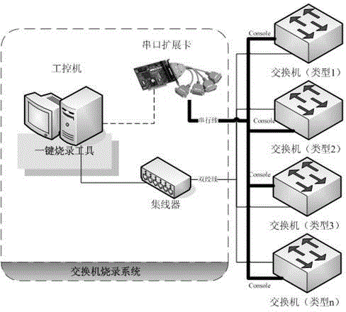
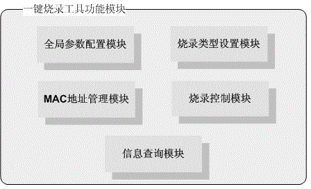
[0021] Such as figure 1 As shown, the system mainly includes an industrial computer installed with a one-key programming tool, a serial port expansion card, and a hub. The interface of the serial port expansion card is a PCI interface, which can be installed in the industrial computer and used to virtualize more (more than 2) serial ports that can be independently controlled. Among them, the hub should have at least 4 RJ45 ports, which are used to connect the industrial computer and multiple switches to be burned, so that the upgrade program can be transmitted to multiple target switches at the same time during the burning process. figure 1 The shown system uses 4 serial port expansion cards and 4 network port hubs, which means that this system can burn 4 switches at the same tim...


PUM


Abstract

The invention relates to a system for simultaneously realizing one-button burning on multiple switches, a method thereof and the corresponding switches. The system comprises a computer arranged with a one-button burning tool, at least a serial port expansion member and a bench common exchange apparatus. The system can simultaneously sent correlation operation instructions to multiple switches to be burned through the serial port expansion member and read the return content; and then is simultaneously connected to the internet access of multiple switches to be burned through the common exchange apparatus, and then simultaneously transmits the upgrade files to the multiple switches to be burned; the one-button burning tool arranged on the computer can be used for starting several tasks and control burning operation on multiple switches. The system can greatly increase the production efficiency of switch burning, by management of MAC address and batch number, faults such as repetition and omission due to artificial operation can be reduced.

Description

technical field [0001] The invention relates to the technical field of switch batch programming. Background technique [0002] Before the switch leaves the factory, it is necessary to burn the kernel file (including Boot file, Bin file) and MAC address into it. The traditional switch burning method is basically a manual operation, including "starting the FTP server", "starting the hyperterminal ", "Enter Boot Password", "Display Burning Menu", "Modify Boot Burning Parameters", "Upgrade Boot File", "Modify Bin Burning Parameters", "Write MAC Address" and "Query Status After Restart" Waiting for 9 major steps, each of which requires the operator to manually input one or more necessary parameters, and only one switch can be burned at a time, the operation cycle is long, and manual operation is easy to make mistakes; in the "burning MAC address In the step of ", the operator needs to additionally record and share the programmed MAC address in some way to prevent multiple uses o...

Claims


Application Information

Patent Timeline
IPC IPC(8): G11C8/16H04L12/931
Inventor 李文云杨国文
Owner TRANSCEND COMM BEIJING
Learn More