Drainage floor tile

A technology of floor tiles and drainage boards, applied to roads, pavements paved with prefabricated blocks, pavement details, etc., can solve problems such as drainage pipe blockage, achieve smooth drainage, save investment, and reduce loads

Inactive Publication Date: 2015-03-18
贺桂荣
View PDF0 Cites 2 Cited by
  • Summary
  • Abstract
  • Description
  • Claims
  • Application Information

AI Technical Summary

Problems solved by technology

[0003] The purpose of the present invention is to provide a drainage floor tile, which solves the problem that the drainage cover in the prior art is easy to block the drainage pipe

Method used


Image

  • Drainage floor tile

Examples


Embodiment Construction

[0010] The present invention will be described in detail below in conjunction with the accompanying drawings and specific embodiments.

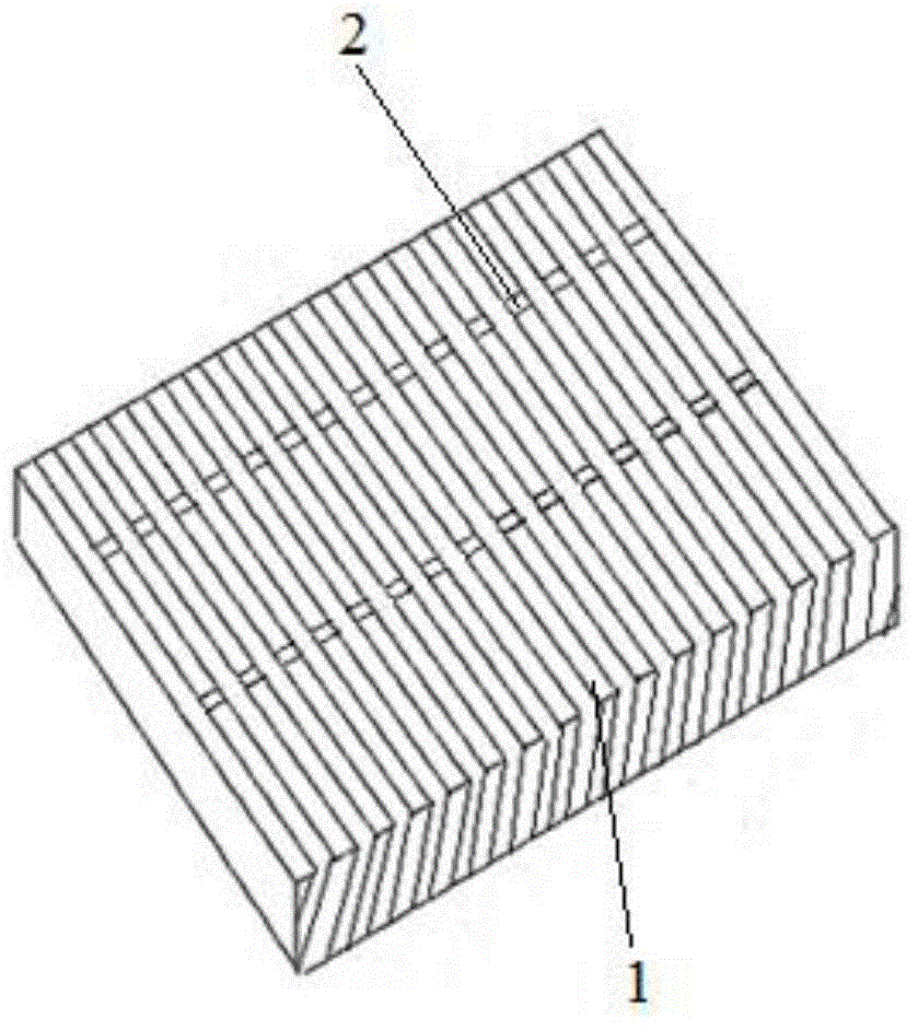
[0011] The structure of the drainage floor tile of the present invention includes a drainage board 1 connected by a drainage horizontal pipe 2 . This design maximizes the drainage space, good water filtration, smooth drainage, saving time and effort.

[0012] The drainage board 1 is arranged at an angle of 45° to 65° with the horizontal direction. The inclined design not only makes it difficult for garbage and other sundries to enter, but also makes it easy for women wearing stilettos to walk on it carefully.

[0013] Through the above method, the present invention solves the problem in the prior art that the drain cover is easy to block the drain pipe. Moreover, the drainage floor tile is strong, firm and light in weight, which can reduce the load of the building.


PUM


Abstract

The invention discloses a drainage floor tile, which comprises drainage plates, wherein the drainage plates are connected with one another through horizontal drainage pipes. The problem that a drainage pipe is likely to be plugged through a drainage cover in the prior art is solved. In addition, the drainage floor tile is good in drainability and smooth to drain and has time-saving and effort-saving effects, the investment is saved, and the load of a building can be reduced; in addition, the drainage floor tile adopts oblique design, so that women wearing high-heeled shoes can walk on the drainage floor tile without worry.

Description

technical field [0001] The invention belongs to the technical field of construction equipment, and in particular relates to a drainage floor tile. Background technique [0002] With the development of global urbanization, the drainage system plays an increasingly important role in the sustainable development of society. The natural drainage of rainwater is not the ultimate goal of the drainage system, but the beginning of a more arduous governance work. A good drainage system plays an important role in the construction period of civil engineering and the normal use and life of structures. The traditional way of drainage is to use the inclination angle of the urban road surface to drain water to the low-lying drainage pipe. The drainage pipe is covered with a drainage cover. The common drainage cover is connected by multiple metal strips. For the convenience of drainage, the relative The gap between two adjacent metal strips is designed to be relatively large, so that sundri...

Claims


Application Information

Patent Timeline
Patent Type & Authority Applications(China)
IPC IPC(8): E01C5/04E01C11/24
CPCE01C11/225E01C5/04E01C2201/20
Inventor 贺桂荣
Owner 贺桂荣
Why Eureka
Try Eureka