Target assembly and manufacturing method thereof

A manufacturing method and target technology, which are applied in manufacturing tools, metal material coating process, ion implantation plating, etc., can solve problems such as unfavorable operations and difficult discharge, and achieve the goal of reducing welding defects and improving welding bonding rate. Effect

Active Publication Date: 2015-03-18
KONFOONG MATERIALS INTERNATIONAL CO LTD
View PDF6 Cites 10 Cited by
  • Summary
  • Abstract
  • Description
  • Claims
  • Application Information

AI Technical Summary

Problems solved by technology

figure 2 The thickness of the medium target 10B is greater than the thickness of the ordinary target, although the sputtering life of the target assembly can be increased, but after the target 10B is welded to the back plate 20B, the target 10B will be embedded in the welding surface of the back plate 20B, At this time, the residual gas between the target and the welding surface is more difficult to discharge than ordinary target components; moreover, the welding line 25B between the target 10B and the back plate 20B cannot be exposed, which is not conducive to various operations in the welding process

Method used


Image

  • Target assembly and manufacturing method thereof
  • Target assembly and manufacturing method thereof
  • Target assembly and manufacturing method thereof

Examples


Embodiment Construction

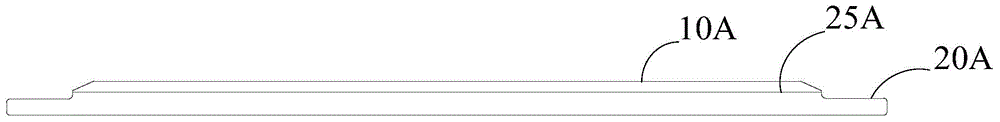
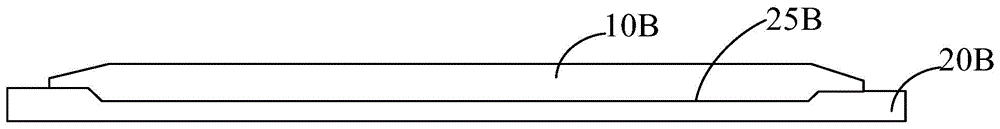
[0036] As described in the background technology, in the existing manufacturing method of target components, during the process of welding the target and the back plate, there is likely to be gas residue between the target and the back plate, and these residual gases are likely to cause the target , The reduction of the bonding rate of the back plate welding.

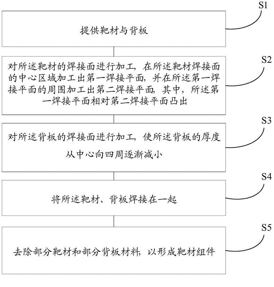
[0037] In order to solve the technical problem, the present invention provides a method for manufacturing a target assembly. refer to image 3 , shows a schematic flow chart of an embodiment of the manufacturing method of the target assembly of the present invention. The manufacturing method generally includes the following steps:

[0038] Step S1, providing a target and a back plate;

[0039] Step S2, processing the welding surface of the target, machining a first welding plane in the central area of ​​the target welding surface, and machining a second welding plane around the first welding plane, wherein, The firs...


PUM

PropertyMeasurementUnit
diameteraaaaaaaaaa

Abstract

The invention discloses a manufacturing method for a target assembly. The manufacturing method comprises the following steps: providing a target and a back plate; processing a welding surface of the target, processing a first welding plane in a central region of the welding surface of the target, and processing a second welding plane around the first welding plane, wherein the first welding plane is protruded relative to the second welding plane; processing a welding surface of the back plate to enable the thickness of the back plate to be gradually reduced from the center to the surrounding; welding the target and the back plate together; removing part of a material of the target and part of a material of the back plate so as to form the target assembly. The invention also provides a target assembly. The target assembly comprises the target and the back plate; the welding surface of the target is embedded into the welding surface of the back plate. According to the method provided by the invention, retained gas between the target and the back plate is further exhausted, so that the target yield is increased. Furthermore, the invention also provides the target assembly obtained by the method.

Description

technical field [0001] The invention relates to the field of semiconductor manufacturing, in particular to a target component and a manufacturing method thereof. Background technique [0002] Sputter coating is a common process in semiconductor manufacturing. The quality of the target has an important influence on the performance of the sputtered film, and with the increase of the size of the sputtering target and the sputtering power, the processing requirements of the sputtering target are getting higher and higher. The processing technology of large-area targets has become a key technology in the manufacture of target components. [0003] In the sputtering coating process, targets can be divided into metal targets, ceramic targets and alloy targets, among which alloy targets are more common targets. At present, the target component usually uses diffusion bonding (DB, Diffusion Bonding) to realize the combination of the target and the back plate. [0004] Diffusion weld...

Claims


Application Information

Patent Timeline
Patent Type & Authority Applications(China)
IPC IPC(8): B23K20/24B23K20/14B23K20/00C23C14/34
CPCB23K20/023B23K20/14B23K20/24C23C14/3407
Inventor 姚力军相原俊夫大岩一彦潘杰王学泽陈玉蓉
Owner KONFOONG MATERIALS INTERNATIONAL CO LTD
Why Eureka
Try Eureka