
Electronic blackboard and imaging pen

An electronic blackboard and imaging technology, applied in the directions of electrical operation teaching aids, optics, instruments, etc., can solve the problems of handwriting that cannot display multiple colors, time delay, etc., and achieve the effect of rich functions, easy manufacturing and low energy consumption.

Active Publication Date: 2017-12-01
JIANGHAN UNIVERSITY
View PDF12 Cites 0 Cited by
  • Summary
  • Abstract
  • Description
  • Claims
  • Application Information

AI Technical Summary

Problems solved by technology

[0006] In order to solve the problem that the writing process of the existing electronic blackboard is prone to delay and cannot present handwriting of various colors, an embodiment of the present invention provides an electronic blackboard and an imaging pen

Method used


Image

  • Electronic blackboard and imaging pen
  • Electronic blackboard and imaging pen
  • Electronic blackboard and imaging pen

Examples


Embodiment 1

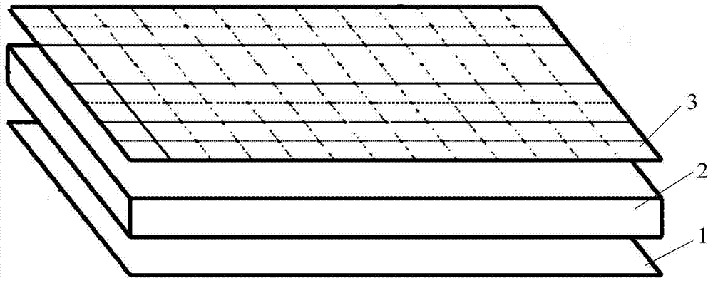
[0033] An embodiment of the present invention provides an electronic blackboard, see figure 1 , the electronic blackboard comprises: a lower pole plate 1, an electrode capsule layer 2 uniformly coated on the lower pole plate 1, an upper pole plate 3 covering the electrode capsule layer 2, the lower pole plate 1, the electrode capsule layer 2 and the upper pole plate The frame in which the pole plates 3 are fixed together ( figure 1 Not identified in ), and the power supply module for the lower plate 1 ( figure 1 Not marked in ), the upper surface of the upper plate 3 is provided with a plurality of dividing grooves, the dividing grooves divide the upper plate 3 into a plurality of subunits, the subunits are evenly coated with a transparent conductive film, the electrode capsule layer 2 includes microcapsules A body comprising white positively charged particles, black negatively charged particles, and a colored liquid.

[0034] In this embodiment, a conductive glass film may ...

Embodiment 2

[0055] An embodiment of the present invention provides an imaging pen, which is used in conjunction with the electronic blackboard described in Embodiment 1, see Figure 4 , the imaging pen includes:

[0056] Housing 101, pen head 102, piezoelectric ceramic group 103 fixed in the pen head 102, drive module 104 installed in the housing 101 and capable of generating tip discharge, used to process the voltage signal generated by the piezoelectric ceramic group 103 and output To the circuit part 105 of the driving module 104, and the voltage control element 106 for controlling the output voltage of the circuit part 105.

[0057] The nib 102 is stretchably and elastically connected to one end of the casing 101, and an extruding part 111 is fixed inside the casing 101, and one end of the extruding part 111 extends into the nib 102 and contacts with the piezoelectric ceramic group 103, and the piezoelectric ceramic group 103 and The circuit part 105 is electrically connected, and th...


PUM


Abstract

The invention discloses an electronic blackboard and an imaging pen, belonging to the technical field of information display. The electronic blackboard includes: a lower electrode plate, an electrode capsule layer, an upper electrode plate, a frame and a power supply module. The upper electrode plate is provided with a plurality of dividing grooves, and the dividing grooves divide the upper electrode plate into a plurality of sub-units, and the sub-units are evenly distributed. Coated with a transparent conductive film, the electrode capsule layer includes microcapsules, and the microcapsules include white positively charged particles, black negatively charged particles, and colored liquid. The invention provides negative charge to the transparent conductive film of the subunit on the upper plate of the electronic blackboard through the imaging pen capable of tip discharge, so as to change the electric field between the upper and lower plates, so as to directly control the imaging of the electrode capsule layer, and the reaction speed is fast; The discharge of the tip of the imaging pen eliminates the electric field between the upper and lower plates, so that the electronic blackboard displays the color of the liquid in the microcapsules, adding a color display and making the electronic blackboard more functional.

Description

technical field [0001] The invention relates to the technical field of information display, in particular to an electronic blackboard and an imaging pen. Background technique [0002] Blackboards and chalks are the most common props in teaching. Traditional blackboards and chalks will generate a lot of dust during the teaching process, which will cause various respiratory diseases such as tuberculosis. At the same time, with the rapid development of multimedia technology, traditional blackboards and chalk can no longer meet the needs of multimedia teaching. In this case, electronic blackboards have emerged as the times require. [0003] The existing electronic blackboard generally adopts an electronic blackboard with an electrophoretic display panel, which is composed of a transparent panel, a precise positioning test layer, an electrophoretic display panel, a driving electrode layer and a backplane in sequence. When the operator writes on the transparent panel with a mouse...

Claims


Application Information

Patent Timeline
Patent Type & Authority Patents(China)
IPC IPC(8): G09B5/02G02F1/167
CPCG02F1/167G09B5/02
Inventor 朱小龙
Owner JIANGHAN UNIVERSITY
Learn More