
Openable Rogowski coil assembly for measuring lightning current in power transmission line

A Rogowski coil and transmission line technology, applied in the field of openable Rogowski coils, can solve the problems of accurate measurement of parameters affecting lightning current, changes in the shape and structure of the winding coil, and the Rogowski coil has no hard shell protection and plasticity, so as to ensure measurement accuracy. and service life, improve mechanical strength and stability, and overcome the inconvenience of on-site installation

Active Publication Date: 2015-03-11
STATE GRID CORP OF CHINA +1
View PDF8 Cites 23 Cited by
  • Summary
  • Abstract
  • Description
  • Claims
  • Application Information

AI Technical Summary

Problems solved by technology

[0003] The traditional Rogowski coils used for transient traveling wave current measurement are mostly complete closed hard structures, that is, closed ring-shaped metal shields with aluminum or copper shells, when used to measure lightning current fault waveforms flowing on transmission lines , since the power transmission wire must pass through the closed coil, it is often necessary to disconnect the measured wire to pass through the Rogowski coil, which brings great inconvenience to the on-site installation of the equipment. The Rogowski coil has no hard shell protection and plasticity; for Therefore, some scholars have also proposed a Rogowski coil composed of two semi-circular ring skeletons, but the hinge connection of the section often destroys the integrity of the circular skeleton, and the winding coil is easily broken due to repeated opening and closing wear of the Rogowski coil.
[0004] At present, the technical solution adopted to solve this problem is generally to use a Rogowski coil with a flexible skeleton, which has two main defects: one is that the flexible skeleton is wound after the transmission wire, because its shape will change with the dance of the wire, temperature and pressure changes , leading to changes in the shape and structure of the wound coil, and then changing the structural parameters and electrical parameters of the Rogowski coil, thus affecting the accurate measurement of lightning current parameters
The second is that when winding a coil on a flexible skeleton, it is easy to cause manufacturing process problems such as skeleton deformation, winding coil breakage, and difficulty in precise control of winding uniformity; in addition, in order to improve the electromagnetic anti-interference of the Rogowski coil, it is often necessary Wind a loop along the flexible skeleton first. After the coil is wound, it is difficult to ensure that the loop is completely parallel to the flexible skeleton, which causes a large error between the structural parameters of the Rogowski coil and the design parameters.

Method used


Image

  • Openable Rogowski coil assembly for measuring lightning current in power transmission line
  • Openable Rogowski coil assembly for measuring lightning current in power transmission line
  • Openable Rogowski coil assembly for measuring lightning current in power transmission line

Examples


Embodiment 1

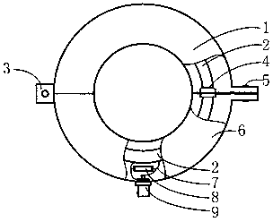
[0028] figure 1 It is a schematic diagram of the overall structure of the present invention, the left end of the semicircular upper coil housing 1 and the left end of the lower coil housing 6 are hinged together through the hinge 3, and the right end of the upper coil housing 1 and the right end of the lower coil housing 6 are screwed together. The nuts 5 are connected to form a circle; the inner wall of the upper coil shell 1 and the inner wall of the lower coil shell 6 are fixed with a semicircular flexible Rogowski coil thread skeleton 2, which is processed on the side wall of the flexible Rogowski coil thread skeleton 2 There is a threaded groove 10, and the winding coil 11 is evenly wound in the threaded groove 10 on the flexible Rogowski coil threaded skeleton 2, and the outer layer of the flexible Rogowski coil threaded skeleton 2 and the wound coil 11 is covered with an insulating sleeve 12, The inner shielding layer 13 is wrapped on the outer layer of the insulating s...

Embodiment 2

[0039] The structure of embodiment 2 is basically the same as embodiment 1, the difference is:

[0040] The threaded groove 10 on the flexible Rogowski coil threaded skeleton 2 is a unidirectional threaded groove, and the groove spacing between two unidirectional threaded grooves is twice the diameter of the unidirectional threaded groove.

[0041] The groove pitch of the unidirectional thread groove is equidistant.

Embodiment 3

[0043] In this embodiment, the value of the integral resistor 8 is relatively large, 510Ω, forming an external integral Rogowski coil. The integral resistor 8 and the integral circuit composed of an operational amplifier jointly restore the differential signal induced by the Rogowski coil, so that the output signal It is proportional to the measured current.


PUM

PropertyMeasurementUnit
thicknessaaaaaaaaaa

Abstract

The invention discloses an openable Rogowski coil assembly for measuring lightning current in a power transmission line. The openable Rogowski coil comprises an upper coil shell, a lower coil shell, a flexible Rogowski coil spiral bobbin, a winding coil, an insulating sleeve, an inner shielding layer, a heat shrinkable tube and the like. The winding coil evenly winds in a spiral groove of the flexible Rogowski coil spiral bobbin; the insulating sleeve, the inner shielding layer and the heat shrinkable tube sleeve the flexible Rogowski coil spiral bobbin and the winding coil in sequence. The flexible Rogowski coil spiral bobbin with a screw thread and a positive-reverse double-layer winding method are adopted, uniform winding of the winding coil can be guaranteed, electromagnetic interference resistance of the Rogowski coil can be improved, and the problem that the traditional closed hard-structure Rogowski coil is inconvenient to mount on the site is effectively solved. An epoxy resin layer filled in a cavity of a bobbin shell helps improve overall mechanical strength and stability of the Rogowski coil, deformation of the Rogowski coil caused by accumulated external force can be avoided, and measuring precision and service life are guaranteed for the Rogowski coil.

Description

technical field [0001] The invention relates to the related technical field of electronic current transformers, in particular to an openable Rogowski coil for lightning current measurement of transmission lines. Background technique [0002] Lightning strike fault is one of the most frequent accidents of transmission line tripping accidents. Accurate lightning parameters are not only the basis of lightning protection design of power grid, but also the premise of studying lightning characteristics and analyzing lightning accidents. Therefore, the measurement of lightning parameters is very important in power grid lightning protection Because the Rogowski coil has the advantages of wide frequency range, good linearity, simple structure, and strong anti-interference ability, it is often used to measure lightning current parameters of transmission line lightning faults. [0003] The traditional Rogowski coils used for transient traveling wave current measurement are mostly compl...

Claims


Application Information

Patent Timeline
Patent Type & Authority Applications(China)
IPC IPC(8): G01R15/18H01F5/00
Inventor 徐春营谢玲玲王凯睿曾庆汇
Owner STATE GRID CORP OF CHINA
Learn More