Tool clamping chuck

A tool chuck and collet technology, applied in the direction of the chuck, etc., can solve the problems of large vibration of the tool chuck, reduction of tool clamping force, and affecting the normal operation of the tool chuck

Inactive Publication Date: 2015-03-11
常州市永联管桩有限公司
View PDF0 Cites 7 Cited by
  • Summary
  • Abstract
  • Description
  • Claims
  • Application Information

AI Technical Summary

Problems solved by technology

When working, the tool holder rotates at a high speed, and the tool holder will generate large vibrations. Under long-term work, the nut will loosen due to vibration, and the clamping force of the tool holder on the tool will be reduced, which will affect the normal operation of the tool holder. , affect the normal work of the tool

Method used


Image

  • Tool clamping chuck

Examples


Embodiment Construction

[0011] The present invention will be further described below in conjunction with the accompanying drawings and specific embodiments.

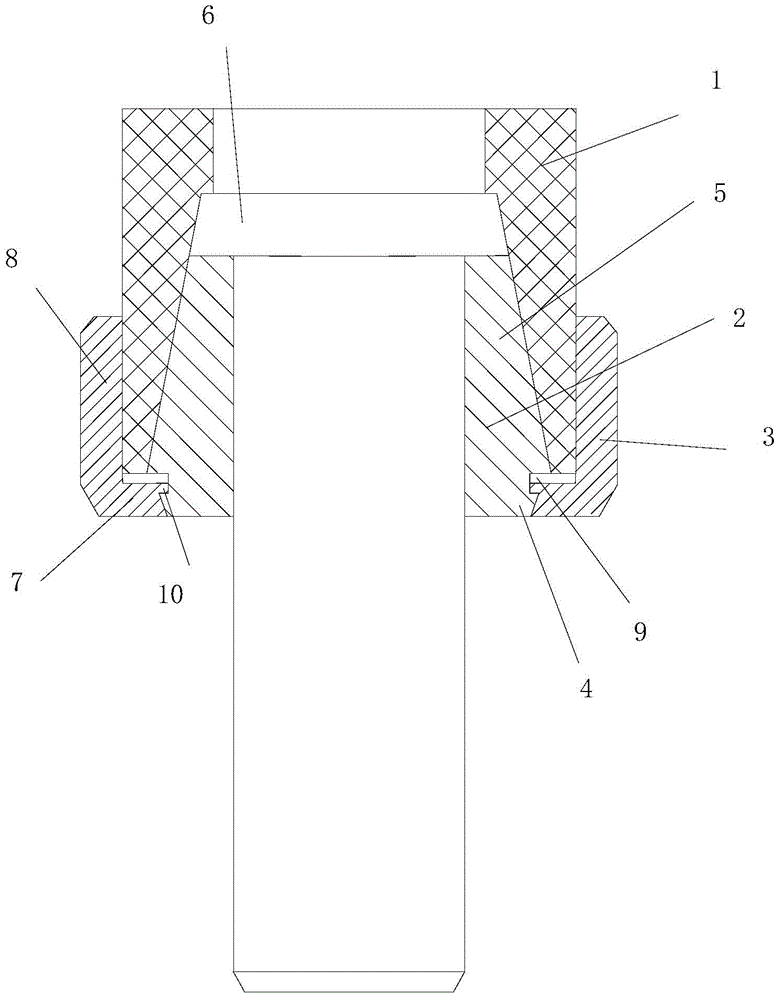
[0012] like figure 1 , a tool chuck, comprising a tool bar 1, a collet 2, and a nut 3, the collet is divided into a front section 4 and a rear section 5, the outer surface of the rear section of the collet is a conical surface, and the tool bar is axially provided with The inner taper hole A6 that matches the outer taper of the rear section of the collet, the front part of the tool rod is provided with an external thread A, the rear section of the collet is clamped in the inner taper hole A, and the axial center of the nut is provided with A through hole, the rear section 8 of the through hole is provided with an internal thread A, the nut is arranged on the front end of the collet and is threadedly connected with the external thread A of the knife rod through the internal thread A, the outer surface of the front section of the collet is a coni...


PUM


Abstract

The invention relates to a tool clamping chuck. The tool clamping chuck comprises a toolbar, a collet chuck and a nut; the collet chuck is divided into a front section and a rear section, wherein the rear section is clamped into the toolbar; external threads A are arranged in the front part of the toolbar; a through hole is arranged in the axial center of the nut, and internal threads A are arranged in the rear section of the through hole; the nut is arranged at the front end of the collet chuck and is connected with the external threads A in the toolbar through the internal threads A; the outer surface of the front section of the collet chuck is a cone surface in which external threads B are arranged; an inner cone hole B, which is equipped with internal threads B and adapted to the cone surface of the front section of the collet chuck, is formed in the front section of the through hole; the front section of the collet chuck is connected with the front section of the through hole in the nut through threads; and the internal threads B in the front section of the through hole in the nut are in the direction opposite to the internal threads A in the rear section of the through hole, and while the threads in the rear section of the through hole in the nut are in the direction opposite to the rotating direction of the tool clamping chuck. The tool clamping chuck adopting the scheme above has the advantages that the threaded connections in two parts enable stable connection of all components of the clamping chuck, and the clamping force and stability of the clamping chuck are effectively improved.

Description

technical field [0001] The invention relates to the field of machine tool clamping components, in particular to a tool clamp. Background technique [0002] The currently used tool chuck generally includes a tool holder, a collet, and a nut. The handle of the tool is inserted into the collet, the collet is clamped in the tool rod, the nut is threaded with the tool rod, and the nut tightens the collet during the tightening process. Pushing forward, the collet is forced to shrink in diameter, clamping the shank of the tool. When working, the tool holder rotates at a high speed, and the tool holder will generate large vibrations. Under long-term work, the nut will loosen due to vibration, and the clamping force of the tool holder on the tool will be reduced, which will affect the normal operation of the tool holder. , affecting the normal work of the tool. Contents of the invention [0003] In view of the above problems, the object of the present invention is to provide a to...

Claims


Application Information

Patent Timeline
IPC IPC(8): B23B31/107
CPCB23B31/023
Inventor 蒋树松
Owner 常州市永联管桩有限公司
Why Eureka
Try Eureka