A Fault Phase Selection Method Using the Gradient Sum of Phase Currents
A technology of fault phase selection and current gradient, applied in the direction of fault location, etc., can solve problems such as quick movement or insufficient sensitivity
- Summary
- Abstract
- Description
- Claims
- Application Information
AI Technical Summary
Problems solved by technology
Method used
Image
Examples
Embodiment 1
[0120] Example 1: Single phase to ground fault
[0121] by figure 1 The power transmission system shown is taken as an example, and its line parameters are as follows: the total length of the line is 150km for the PM section, 150km for the MN section, and 220km for the NQ end. Fault setting: set the phase A ground fault on line MN 70km away from the M side, the initial phase angle of the fault is 90°, the transition resistance is 50Ω, the sampling rate is 20kHz, and the fault point 3 is taken within the time interval of 0.1400s to 0.2200s phase current.
[0122] 1 According to the set fault, according to step 1 in the manual, get the three-phase current data through the measuring terminal, and calculate the zero-mode current data.
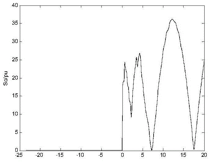
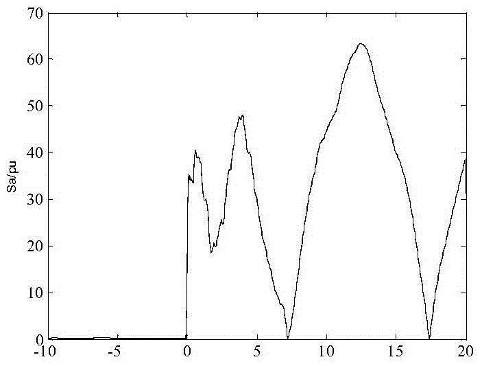
[0123] 2 Construct the current gradient according to steps 2 and 3 in the manual, and calculate the sum of the three-phase current gradients based on the three-phase current and the zero-mode current. The obtained results are as follows Figure ...
Embodiment 2
[0130] Example 2: Short-circuit fault between two phases of BC
[0131] by figure 1 The power transmission system shown is taken as an example, and its line parameters are as follows: the total length of the line is 150km for the PM section, 150km for the MN section, and 220km for the NQ end. Fault setting: A BC two-phase short-circuit fault occurs 149km away from the M side on the line MN, the initial phase angle of the fault is 90°, the transition resistance is 50Ω, the sampling rate is 20kHz, and the three-phase current at the fault point is taken within the time interval of 0.1400s to 0.2200s .
[0132] (1) According to the set fault, according to step 1 in the manual, get the three-phase current data through the measuring terminal, and calculate the zero-mode current data.
[0133] (2) Construct the current gradient according to step 2 and step 3 in the manual, and calculate the sum of the three-phase current gradients based on the three-phase current and the zero-mode ...
Embodiment 3
[0140] Example 3: AC two-phase ground fault
[0141] by figure 1The power transmission system shown is taken as an example, and its line parameters are as follows: the total length of the line is 150km for the PM section, 150km for the MN section, and 220km for the NQ end. Fault setting: An AC two-phase ground fault (AC-G) occurs 90km away from the M side on the line MN, the initial phase angle of the fault is 60°, the transition resistance is 10Ω, the sampling rate is 20kHz, and the sampling time range is 0.1400s to 0.2200s Three-phase current within the fault point.
[0142] (1) According to the set fault, according to step 1 in the manual, get the three-phase current data through the measuring terminal, and calculate the zero-mode current data.
[0143] (2) Construct the current gradient according to step 2 and step 3 in the manual, and calculate the sum of the three-phase current gradients based on the three-phase current and the zero-mode current. The obtained results a...
PUM
 Abstract
Description
Claims
Application Information
 - R&D
- Intellectual Property
- Life Sciences
- Materials
- Tech Scout
- Unparalleled Data Quality
- Higher Quality Content
- 60% Fewer Hallucinations
Browse by: Latest US Patents, China's latest patents, Technical Efficacy Thesaurus, Application Domain, Technology Topic, Popular Technical Reports.
© 2025 PatSnap. All rights reserved.Legal|Privacy policy|Modern Slavery Act Transparency Statement|Sitemap|About US| Contact US: help@patsnap.com


