
Fault phase selection method utilizing phase current gradient sums

A technology of fault phase selection and current gradient, applied in the direction of fault location, etc., can solve problems such as quick movement or insufficient sensitivity

Active Publication Date: 2015-03-04
KUNMING UNIV OF SCI & TECH
View PDF5 Cites 11 Cited by
  • Summary
  • Abstract
  • Description
  • Claims
  • Application Information

AI Technical Summary

Problems solved by technology

[0004] The technical problem to be solved by the present invention is to overcome the problem of insufficient quickness or sensitivity of the existing fault phase selection method, and propose a fault phase selection method using the phase current gradient sum

Method used


Image

  • Fault phase selection method utilizing phase current gradient sums
  • Fault phase selection method utilizing phase current gradient sums
  • Fault phase selection method utilizing phase current gradient sums

Examples


Embodiment 1

[0120] Example 1: Single phase to ground fault

[0121] by figure 1 The power transmission system shown is taken as an example, and its line parameters are as follows: the total length of the line is 150km for the PM section, 150km for the MN section, and 220km for the NQ end. Fault setting: set the phase A ground fault on line MN 70km away from the M side, the initial phase angle of the fault is 90°, the transition resistance is 50Ω, the sampling rate is 20kHz, and the fault point 3 is taken within the time interval of 0.1400s to 0.2200s phase current.

[0122] 1 According to the set fault, according to step 1 in the manual, get the three-phase current data through the measuring terminal, and calculate the zero-mode current data.

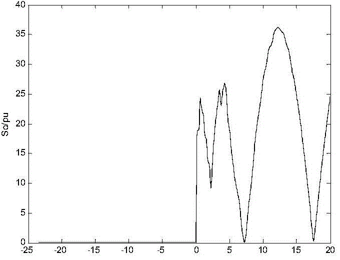
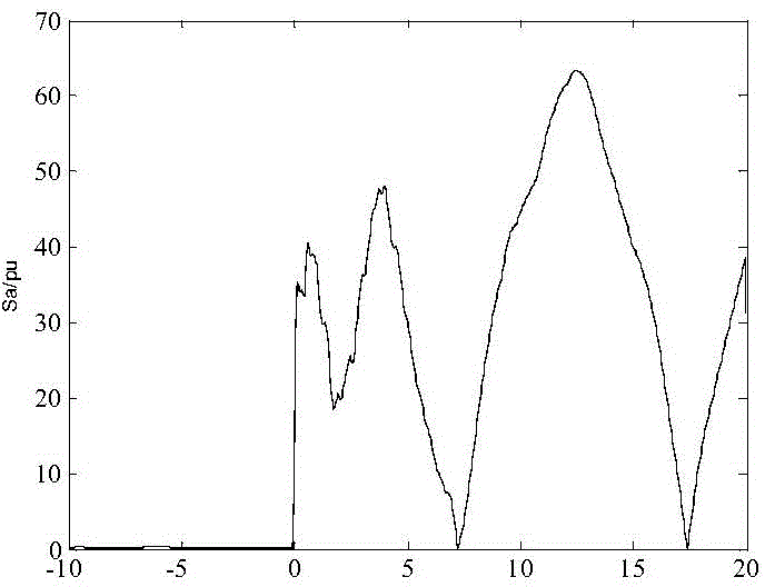
[0123] 2 Construct the current gradient according to steps 2 and 3 in the manual, and calculate the sum of the three-phase current gradients based on the three-phase current and the zero-mode current. The obtained results are as follows Figure ...

Embodiment 2

[0130] Example 2: Short-circuit fault between two phases of BC

[0131] by figure 1 The power transmission system shown is taken as an example, and its line parameters are as follows: the total length of the line is 150km for the PM section, 150km for the MN section, and 220km for the NQ end. Fault setting: A BC two-phase short-circuit fault occurs 149km away from the M side on the line MN, the initial phase angle of the fault is 90°, the transition resistance is 50Ω, the sampling rate is 20kHz, and the three-phase current at the fault point is taken within the time interval of 0.1400s to 0.2200s .

[0132] (1) According to the set fault, according to step 1 in the manual, get the three-phase current data through the measuring terminal, and calculate the zero-mode current data.

[0133] (2) Construct the current gradient according to step 2 and step 3 in the manual, and calculate the sum of the three-phase current gradients based on the three-phase current and the zero-mode ...

Embodiment 3

[0140] Example 3: AC two-phase ground fault

[0141] by figure 1The power transmission system shown is taken as an example, and its line parameters are as follows: the total length of the line is 150km for the PM section, 150km for the MN section, and 220km for the NQ end. Fault setting: An AC two-phase ground fault (AC-G) occurs 90km away from the M side on the line MN, the initial phase angle of the fault is 60°, the transition resistance is 10Ω, the sampling rate is 20kHz, and the sampling time range is 0.1400s to 0.2200s Three-phase current within the fault point.

[0142] (1) According to the set fault, according to step 1 in the manual, get the three-phase current data through the measuring terminal, and calculate the zero-mode current data.

[0143] (2) Construct the current gradient according to step 2 and step 3 in the manual, and calculate the sum of the three-phase current gradients based on the three-phase current and the zero-mode current. The obtained results a...


PUM


Abstract

The invention relates to a fault phase selection method utilizing phase current gradient sums and belongs to the power system relay protection technical field. The method comprises the following steps that: a measuring end obtains three-phase current and zero-mode current gradient sums after a power transmission line fault is calculated; after normalization is performed on the three-phase current and zero-mode current gradient sums, the three-phase current gradient sums are sorted into an order of s1, s2 and s3; and whether the fault is a grounding fault is determined according to the zero-mode current gradient sums, if the fault is a non-grounding fault, the absolute value of s1-s2 is larger than a set threshold value, and the fault is a three-phase short-circuiting fault, otherwise, the fault is a phase-to-phase fault, and phases corresponding to s1 and s2 are fault phases; if the fault is a grounding fault, s1 / s2 is greater than the set threshold value, the fault is a single-phase grounding fault, and a phase corresponding to s1 is a fault phase, otherwise, the fault is a two-phase grounding fault, and phases corresponding to s1 and s2 are fault phases. As indicated by a large quantity of simulation analysis, the fault phase selection method utilizing the phase current gradient sums can reliably select fault phases. The reliability of the fault phase selection method is not affected by fault positions, transition resistance and small fault angles, and therefore, the fault phase selection method has excellent effects.

Description

technical field [0001] The invention relates to a fault phase selection method using the gradient sum of phase currents, and belongs to the technical field of electric power system relay protection. Background technique [0002] In high-voltage transmission lines, single-phase reclosing and integrated reclosing are used to improve system stability. When a single-phase fault occurs on the transmission line, single-phase tripping and single-phase reclosing are realized; when multi-phase faults occur, three-phase tripping and three-phase reclosing are realized. Therefore, after the transmission line fails, the fault phase relationship can be accurately and quickly selected The correct action of the transmission line distance protection and automatic reclosing has a significant impact on strengthening the correctness and reliability of the transmission line relay protection action. [0003] The traditional fault phase selection method for high-voltage transmission lines is main...

Claims


Application Information

Patent Timeline
Patent Type & Authority Applications(China)
IPC IPC(8): G01R31/08
Inventor 束洪春白冰高利杨竞及
Owner KUNMING UNIV OF SCI & TECH
Learn More