
Non-contact ultrasonic detection method for storage tank floor corrosion based on dynamic wavelet fingerprint technology

A technology of dynamic wavelet fingerprint and storage tank floor, which is applied in the analysis of solids using sonic/ultrasonic/infrasonic waves, material analysis using sonic/ultrasonic/infrasonic waves, and measurement devices, etc., can solve the problems of high cost, safe and economical operation of storage tanks, Problems such as missed inspection and over-inspection can improve inspection efficiency, avoid corrosion measurement errors, and reduce inspection costs.

Inactive Publication Date: 2017-04-12
CHINA SPECIAL EQUIP INSPECTION & RES INST +1
View PDF7 Cites 0 Cited by
  • Summary
  • Abstract
  • Description
  • Claims
  • Application Information

AI Technical Summary

Problems solved by technology

Although these methods can avoid some leakage accidents caused by corrosion, but due to the need to stop production for detection, the detection time is long, the cost is high, and the determination of the maintenance object is blind, which is easy to cause missed detection and over-inspection, which affects the safe and economical operation of the storage tank. bring hidden danger

Method used


Image

  • Non-contact ultrasonic detection method for storage tank floor corrosion based on dynamic wavelet fingerprint technology
  • Non-contact ultrasonic detection method for storage tank floor corrosion based on dynamic wavelet fingerprint technology
  • Non-contact ultrasonic detection method for storage tank floor corrosion based on dynamic wavelet fingerprint technology

Examples


Embodiment Construction

[0042] Below in conjunction with concrete experiment the present invention will be further described:

[0043] The implementation process of this experiment includes the following steps:

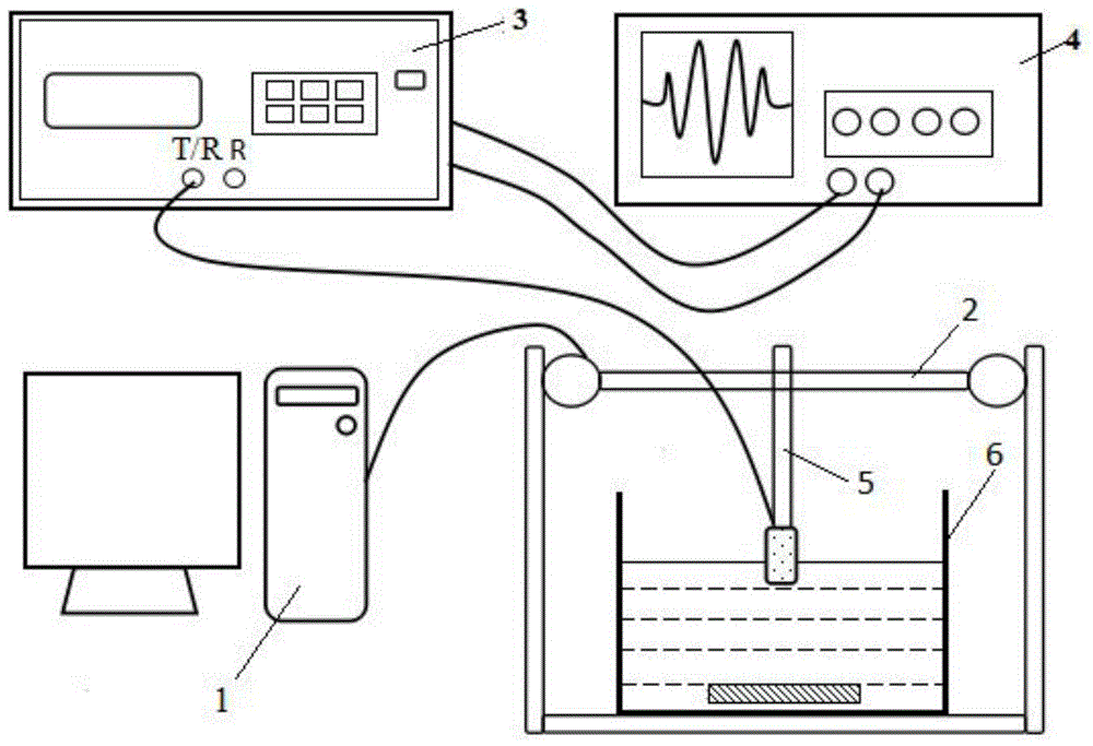
[0044] 1. Experimental system construction: according to figure 2 The system diagram of the detection device shown in the installation test system includes a computer 1, a four-axis linkage scanning platform 2, an ultrasonic pulse transmitter receiver 3, a digital oscilloscope 4, a water immersion non-focus probe with a center frequency of 5MHz 5, 45cm×35cm× 25cm transparent glass sink6. The four-axis linkage scanning platform 2 is connected with the computer 1, and the water immersion non-focus probe 5 with a center frequency of 5 MHz is fixed on the four-axis linkage scanning platform 2, and the optimal position in the Z direction is selected to remain unchanged, and the probe can be changed by a stepping motor The position in the X and Y directions. The T / R port of the ultrasonic puls...


PUM

PropertyMeasurementUnit
thicknessaaaaaaaaaa
thicknessaaaaaaaaaa

Abstract

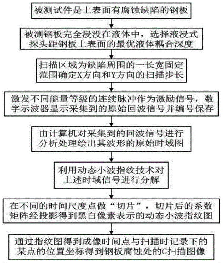
The invention relates to a storage tank bottom plate corrosion noncontact ultrasonic detection method based on a dynamic wavelet fingerprint technology. The method is characterized by comprising the following steps: selecting a steel plate which is smaller than a water trough from a detected test piece; immersing the detected steel plate into the transparent glass water trough, and fixing an immersion-type non-focusing probe on a movable arm of a four-axis linkage scanning platform; determining a scanning step in an X direction and a Y direction; analyzing a group of acquired echo signals by virtue of a computer, and drawing an original time domain chart of waveforms of the echo signals; intercepting a section of the time domain chart as an effective detection zone; resolving an intercepted time domain signal by utilizing wavelet transformation of the dynamic wavelet fingerprint technology; conducting continuous wavelet transformation on a signal after denoising treatment to obtain a wavelet coefficient matrix; conducting normalization processing on the acquired matrix; simultaneously writing an acquired imaging time point and a location coordinate of the time point recorded during the scanning into the matrix to obtain a C scanning image. According to the method, corrosion defects on a storage tank bottom plate can be detected under the situation that a storage tank does not need to be cleaned, so that the detection efficiency can be improved, and the detection cost can be reduced.

Description

technical field [0001] The invention relates to a non-contact ultrasonic detection method for plate structure corrosion defects, in particular to an ultrasonic scanning imaging method for storage tank bottom plate corrosion based on dynamic wavelet fingerprint technology. The method is applicable to the detection of corrosion defects on bottom plates of atmospheric vessels and large storage tanks, and belongs to the field of nondestructive testing. Background technique [0002] As a special equipment for storing crude oil, chemical raw materials and their products, large atmospheric storage tanks are widely used in many fields such as petroleum, chemical industry, national defense, transportation and so on. Because it contains flammable, explosive, highly toxic or corrosive liquids, and operates in a high temperature and high pressure environment for a long time, the bottom plate of the storage tank is prone to corrosion defects. The corrosion state of the storage tank bott...

Claims


Application Information

Patent Timeline
Patent Type & Authority Patents(China)
IPC IPC(8): G01N29/04G01N29/44G01N29/32
Inventor 李兵方舟陈彦泽常予焦敬品
Owner CHINA SPECIAL EQUIP INSPECTION & RES INST
Learn More