
Clamp for metal thin-wall whole segment tube axial tension and compression fatigue test

A fatigue test, metal thin technology, applied in the field of fatigue test, can solve the problems of lock nut stress concentration, reduce the service life of the fixture, fixture damage and other problems, achieve the effect of reducing stress concentration, prolonging the service life and improving the clamping force

Inactive Publication Date: 2015-03-04
HEFEI INSTITUTES OF PHYSICAL SCIENCE - CHINESE ACAD OF SCI
View PDF5 Cites 26 Cited by
  • Summary
  • Abstract
  • Description
  • Claims
  • Application Information

AI Technical Summary

Problems solved by technology

[0005] At present, there are very few fatigue fixtures for full-pipe thin-walled specimens, and the design has the following deficiencies: (1) They all adopt the form of in-line plugs, and only provide clamping force through the outer lock nut , because the inner plug cannot be tightly fitted to the inner wall of the tube, the clamping force provided by this type of clamp is insufficient; (2) only the outer lock nut provides clamping force, which will cause the lock nut to be damaged during the fatigue process. Stress concentration occurs in the middle, and then the fixture is damaged
[0006] It is worth noting that, unlike the traditional water medium, the liquid lead-based alloy is highly corrosive, which will cause strong corrosion to the fixture, thereby reducing the service life of the fixture, so it is necessary to consider when designing the fixture How to reduce the corrosion effect of liquid lead-based alloys on fixtures
[0007] At the same time, the preliminary research shows that there is no report on the fatigue performance data of metal thin-walled pipes in the environment of high-temperature liquid lead-based alloys at home and abroad, and there is no data and experience for reference

Method used


Image

  • Clamp for metal thin-wall whole segment tube axial tension and compression fatigue test
  • Clamp for metal thin-wall whole segment tube axial tension and compression fatigue test
  • Clamp for metal thin-wall whole segment tube axial tension and compression fatigue test

Examples


Embodiment Construction

[0026] The present invention will be further described below in conjunction with the accompanying drawings.

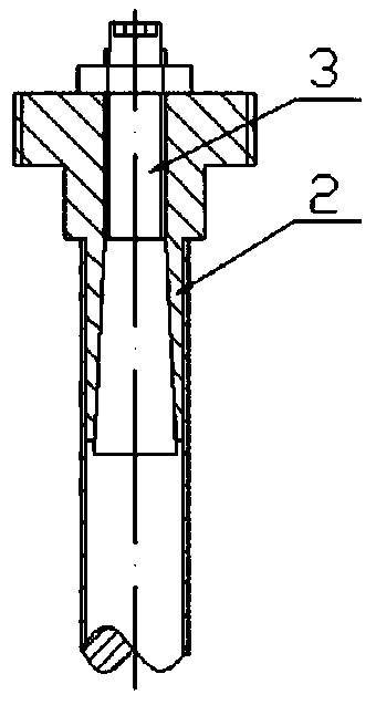
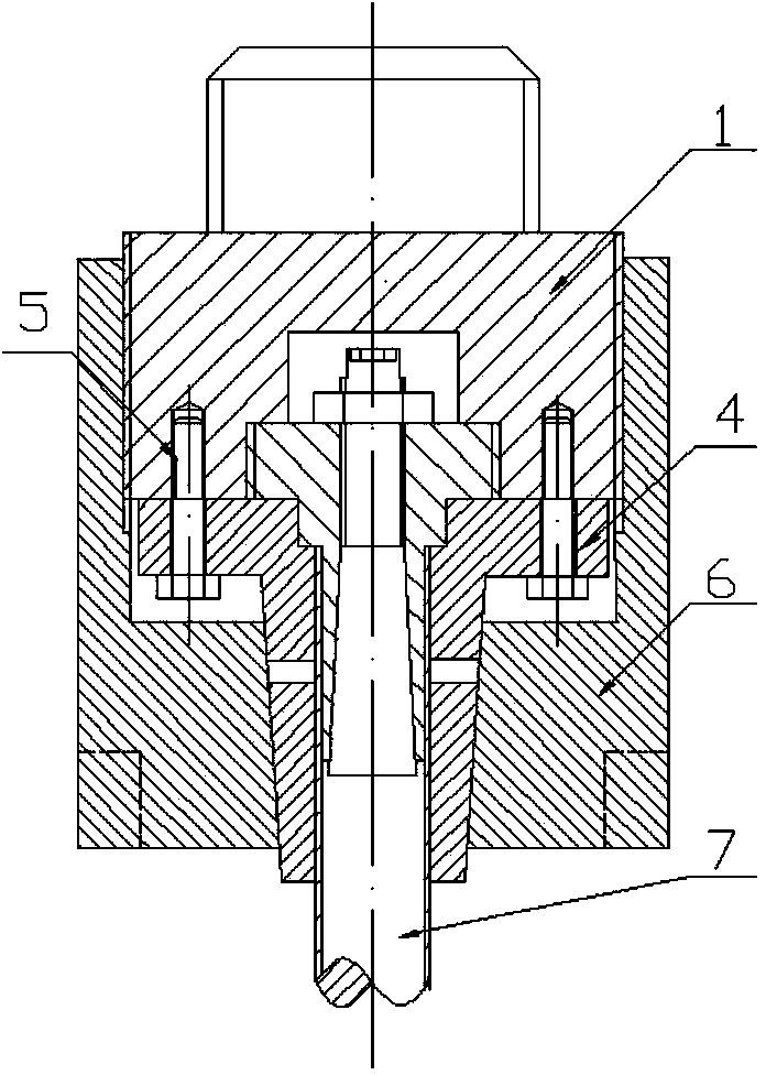
[0027] A jig for axial tension-compression fatigue test of metal thin-walled full-section pipes; including a fixed frame 1, a core sleeve 2, a mandrel 3, an outer jacket 4, bolts 5, and lock nuts 6;

[0028] Core sleeve 2—The upper end of core sleeve 2 is a T-shaped double shoulder with internal thread, and the lower end is a symmetrical four-petal inner cone sleeve. The inner sleeve part of the upper shoulder of core sleeve 2 is internal thread, and the lower end of core sleeve 2 The inner side is a smooth inner cone structure, the outer side of the shoulder at the upper end of the core sleeve 2 is an external thread, and the lower end is a smooth outer wall;

[0029] Mandrel 3—The upper end of the mandrel 3 is a hexagonal nut, the middle end is a screw with external threads, and the lower end is a smooth outer cone shape; the size of the middle end screw of the mandr...


PUM


Abstract

The invention discloses a clamp for metal thin-wall whole segment tube axial tension and compression fatigue test, and is used for realizing the clamping of a thin-wall tubular sample in fatigue test in liquid lead-based alloy environment. The clamp is rotationally connected onto a core sleeve with a taper through a conical core rod, and is assembled on a fixed frame with a reversed T-shaped groove; an outer clamp cover is connected with the fixed frame through a bolt; a lock nut is rotationally connected with the fixed frame till being fastened with the fixed frame to form the clamp. By adopting the clamp, the clamping force to the tubular sample is enhanced through internal and external clamping, the stress concentration of the clamp is reduced, the probability that the liquid lead-based alloy is in direct contact with the interior of the clamp is decreased, the corrosion of the liquid lead-based alloy to main structural components inside the clamp is reduced, and the service life of the clamp is prolonged.

Description

technical field [0001] The invention relates to the field of fatigue tests, in particular to a jig for axial tension-compression fatigue test of metal thin-wall full-section pipes, which is used for axial tension-compression fatigue test of metal thin-wall pipe section samples in high-temperature and liquid lead-based alloy corrosion environments. Background technique [0002] The cladding tube wraps the nuclear fuel and is the first safety barrier of the reactor. China's lead-based research reactor uses liquid lead-based alloy as coolant. When the cladding tube is in service, it needs to withstand fast neutron irradiation in a high-temperature environment, corrosion of coolant, and increasing internal and external stress and other complex working conditions. The cladding is subjected to high temperature, corrosion and cyclic loading, which will lead to fatigue failure or even fracture of the cladding tube. [0003] In order to investigate the fatigue performance of metal m...

Claims


Application Information

Patent Timeline
Patent Type & Authority Applications(China)
IPC IPC(8): G01N3/04
Inventor 陈建伟李京吴庆生韩骞黄群英
Owner HEFEI INSTITUTES OF PHYSICAL SCIENCE - CHINESE ACAD OF SCI
Learn More