
Rotary type safety power strip

A rotary and plug-in technology, applied in the field of plug-in, can solve problems such as loose contact of copper card slots, electric shock casualties, poor contact, etc., and achieve the effects of reducing the risk of electric shock, saving power, and reducing the number of times of plugging and unplugging

Inactive Publication Date: 2015-02-25
WUXI X RES PROD DESIGN & RES
View PDF5 Cites 1 Cited by
  • Summary
  • Abstract
  • Description
  • Claims
  • Application Information

AI Technical Summary

Problems solved by technology

However, the traditional plug-in strip also has some defects. It needs to be plugged and pulled out every time it is used. After a long time, the contact between the plug and the copper sheet slot in the plug-in strip is loose, resulting in poor contact; although there is a power switch button , but it means that all the plugs on the power strip have to be powered on or off at the same time, which is not practical; in addition, the power strip is very attractive to children. Children are naturally playful and often insert their little fingers into the jacks Especially when there is saliva on the little finger, it is more likely to cause electric shock casualties

Method used


Image

  • Rotary type safety power strip
  • Rotary type safety power strip
  • Rotary type safety power strip

Examples


specific Embodiment 1

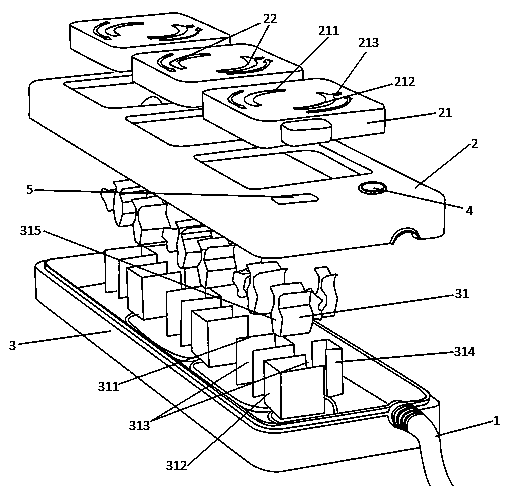
[0015] figure 1 It is a split diagram of a rotating safety plug-in strip; figure 2 It is a usage diagram of a rotary safety plug-in strip; image 3 It is a structural diagram of a rotary safety plug-in card slot. As shown in the figure, a rotary safety plug-in strip includes a wire 1, a top cover 2 and a bottom cover 3, the top cover 2 is provided with a panel 21, and the panel 21 is provided with a There are zero line socket 211 and live line socket 212, and the lower cover 3 of the plug-in row is respectively provided with a neutral line card slot 311 and a live line card slot 312 with a conductive copper sheet 31 which are symmetrical to the neutral line socket 211 and the live line socket 212. One side of the neutral wire socket 211 and the live wire socket 212 respectively extend in opposite directions to form a 30-90° arc-shaped groove 22, the arc-shaped groove 22 of the neutral wire socket and the arc-shaped groove 22 of the live wire socket share a circle center, an...

specific Embodiment 2

[0017] figure 1 It is a split diagram of a rotating safety plug-in strip; figure 2 It is a usage diagram of a rotary safety plug-in strip; image 3 It is a structural diagram of a rotary safety plug-in card slot. As shown in the figure, a rotary safety plug-in strip includes a wire 1, a top cover 2 and a bottom cover 3, the top cover 2 is provided with a panel 21, and the panel 21 is provided with a There are zero line socket 211 and live line socket 212, and the lower cover 3 of the plug-in row is respectively provided with a neutral line card slot 311 and a live line card slot 312 with a conductive copper sheet 31 which are symmetrical to the neutral line socket 211 and the live line socket 212. One side of the neutral wire socket 211 and the live wire socket 212 respectively extend in opposite directions to form a 30-90° arc-shaped groove 22, the arc-shaped groove 22 of the neutral wire socket and the arc-shaped groove 22 of the live wire socket share a circle center, an...

specific Embodiment 3

[0020] figure 1 It is a split diagram of a rotating safety plug-in strip; figure 2 It is a usage diagram of a rotary safety plug-in strip; image 3 It is a structural diagram of a rotary safety plug-in card slot. As shown in the figure, a rotary safety plug-in strip includes a wire 1, a top cover 2 and a bottom cover 3, the top cover 2 is provided with a panel 21, and the panel 21 is provided with a There are zero line socket 211 and live line socket 212, and the lower cover 3 of the plug-in row is respectively provided with a neutral line card slot 311 and a live line card slot 312 with a conductive copper sheet 31 which are symmetrical to the neutral line socket 211 and the live line socket 212. One side of the neutral wire socket 211 and the live wire socket 212 respectively extend in opposite directions to form a 30-90° arc-shaped groove 22, the arc-shaped groove 22 of the neutral wire socket and the arc-shaped groove 22 of the live wire socket share a circle center, an...


PUM


Abstract

The invention relates to a power strip, in particular to a rotary type safety power strip. The rotary type safety power strip comprises a wire, an upper power strip cover and a lower power strip cover; power strip panels are arranged on the upper power strip cover and each provided with a null line jack and a live line jack, the lower power strip cover is provided with null line clamping slots and live line clamping slots with conductive copper sheets, the null line clamping slots and the live line clamping slots are symmetrical with the null line jacks and the live line jacks, one sides of the null line jacks and the live line jacks extend in the opposite directions to form arc slots of 30-90 degrees, the arc slot of each null line jack and the arc slot of the corresponding live line jack are concentric, the null line clamping slots and the live line clamping slots are open in one side in the extending direction of the null line jacks and the live line jacks, and the conductive copper sheets are open in one sides of the openings of the null line clamping slots and the live line clamping slots respectively. The effect of switching on and switching off a power source is achieved by rotating plugs, the power source can be switched off without need of pulling out the plugs or the frequency of plugging is reduced, the danger of electric shock is reduced, and use is safer.

Description

technical field [0001] The invention relates to a plug-in row. Background technique [0002] The power strip plays a very important role in people's daily work and life, and it brings convenience to people's life. However, the traditional plug-in strip also has some defects. It needs to be plugged and pulled out every time it is used. After a long time, the contact between the plug and the copper sheet slot in the plug-in strip is loose, resulting in poor contact; although there is a power switch button , but it means that all the plugs on the socket have to be powered on or off at the same time, which is not practical; in addition, the socket is very attractive to children, who are naturally playful and often insert their little fingers into the socket Especially when there is saliva on the little finger, it is more likely to cause electric shock casualties. SUMMARY OF THE INVENTION [0003] Aiming at the above-mentioned prior art, the technical problem to be solved by ...

Claims


Application Information

Patent Timeline
Patent Type & Authority Applications(China)
IPC IPC(8): H01R13/44H01R13/46H01R13/703
CPCH01R13/44H01R13/46H01R13/703
Inventor 赵成明刘小峰张林娟
Owner WUXI X RES PROD DESIGN & RES
Learn More