Turbidity sensor and turbidity measuring device

A technology of turbidity sensor and measuring device, which is applied in the direction of scattering characteristic measurement, etc., can solve problems such as miniaturization, portability, influence on measurement accuracy, and complicated structure installation, so as to eliminate adverse effects, simplify overall structure design, The effect of improving measurement accuracy

Active Publication Date: 2017-01-25
迦楠森(厦门)商贸有限责任公司
View PDF7 Cites 0 Cited by
  • Summary
  • Abstract
  • Description
  • Claims
  • Application Information

AI Technical Summary

Problems solved by technology

The advantage of this structural design is that the light source, the photoelectric receiving module and the liquid to be measured are non-contact, which can avoid the pollution of the optical receiving window, but there is a requirement for the flow rate of the liquid to be measured. Too fast a flow rate will cause fluctuations in the formed liquid plane , the position of the scattered light will change, so the intensity of the scattered light received by the photodetector will change, affecting the measurement accuracy
The structure and installation of the whole device is relatively complicated, which cannot meet the requirements of miniaturization and portability
Moreover, the above-mentioned defects generally exist in the existing turbidimeters designed based on the surface scattering method

Method used


Image

  • Turbidity sensor and turbidity measuring device
  • Turbidity sensor and turbidity measuring device

Examples


Embodiment Construction

[0019] Below in conjunction with accompanying drawing, technical scheme of the present invention is described in detail:

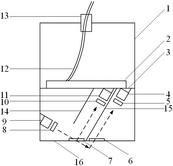
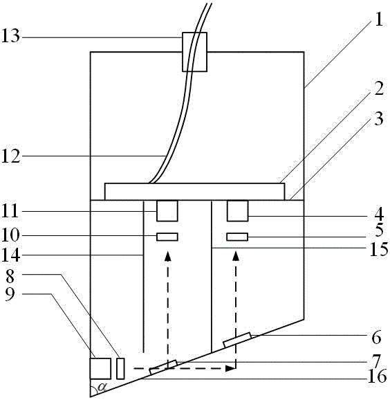
[0020] figure 1 An embodiment of the turbidity measurement device of the present invention is shown, the measurement device comprising a turbidity sensor and a signal processing module. like figure 1 As shown, the turbidity sensor includes a barrel-shaped casing 1. The casing 1 can be in the shape of a round barrel or a square barrel, and the top of the casing 1 can be open or closed. In this embodiment, the bottom surface 16 of the housing 1 is perpendicular to the side wall of the housing, and an LED light source 9 is arranged on the inner side of the side wall of the housing 1 close to the bottom surface 16; The light emitted by 9 is collimated so that parallel light (the dotted line in the figure is the light path) is directed to the bottom surface 16 of the casing, and the included angle between the parallel light and the bottom surface 16 of the ca...


PUM

PropertyMeasurementUnit
wavelengthaaaaaaaaaa
angle of incidenceaaaaaaaaaa
transmittivityaaaaaaaaaa

Abstract

The invention discloses a turbidity sensor and belongs to the technical field of measurement of liquid parameters. The turbidity sensor comprises a shell, a light source and a photoelectric receiving module, wherein the shell is a barrel-shaped shell with a planar bottom surface; the light source is arranged on the inner side of the side wall of the shell and close to the bottom surface of the shell and is capable of emitting parallel light to the bottom surface; an included angle formed between the parallel light and the bottom surface of the shell is 20 degrees; two transparent window mirrors, namely a first window mirror and a second window mirror, which are successively arranged along the light outgoing direction of the light source, are embedded into the bottom surface of the shell; the first window mirror is arranged at the intersection point between light emitted by the light source and the bottom surface of the shell; the photoelectric receiving module comprises two photoelectric detectors, namely a first photoelectric detector and a second photoelectric detector, which are arranged in the inner space of the shell and are used for detecting the density of light incoming from the first window mirror and the second window mirror and perpendicular to the parallel light emitted by the light source, respectively. The invention also discloses a turbidity measurement device. The turbidity sensor and the turbidity measurement device have the advantages of simple structural design, high accuracy and wide measurement range.

Description

technical field [0001] The invention relates to a turbidity sensor, in particular to a turbidity sensor based on a scattered light measurement method, and belongs to the technical field of liquid parameter measurement. Background technique [0002] The turbidity of water is a reflection of the absorption and scattering of light by impurities such as suspended matter, microorganisms and colloidal substances in water with different shapes, sizes and specific gravity, and is an optical property of water samples. With the increasing improvement of people's living standards and the increasing attention to life and health and the natural environment, the monitoring of water turbidity has attracted more and more attention. Turbidity is not only one of the important indicators to measure the quality of water quality, but also an important basis for examining the effect of water treatment. Therefore, the online detection of water turbidity has very important practical significance. ...

Claims


Application Information

Patent Timeline
Patent Type & Authority Patents(China)
IPC IPC(8): G01N21/47G01N21/49
Inventor 常建华王志丹郭跃朱成刚桂诗信
Owner 迦楠森(厦门)商贸有限责任公司
Why Eureka
Try Eureka