
Impact disturbance surrounding rock testing equipment

A test equipment and surrounding rock technology, applied in the field of impact disturbance surrounding rock test equipment

Active Publication Date: 2015-02-25
HUNAN UNIV OF SCI & TECH
View PDF7 Cites 24 Cited by
  • Summary
  • Abstract
  • Description
  • Claims
  • Application Information

AI Technical Summary

Problems solved by technology

[0003] At present, the single-axis to three-axis rock static load test can be realized by adding a side loading device to the common universal material testing machine, and the three-dimensional curve waveform quasi-static loading test method can be realized by using the hydraulic servo system. Hammer realizes the triaxial test equipment for simulating blasting, earthquake and other impact disturbances

Method used


Image

  • Impact disturbance surrounding rock testing equipment
  • Impact disturbance surrounding rock testing equipment
  • Impact disturbance surrounding rock testing equipment

Examples


Embodiment 1

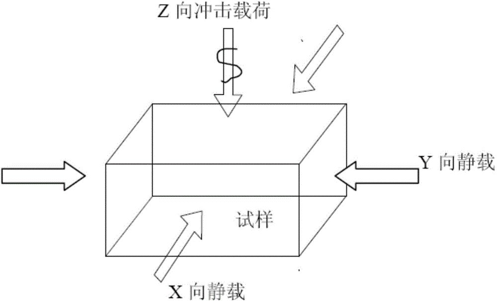
[0018] During the test, according to the size of the rock sample 7 to be tested, the positions of the loading splint 8 in the horizontal Y direction and the loading splint 10 in the horizontal X direction are adjusted, and the center of the rock sample 7 to be tested is aligned with the loading splint 8 in the horizontal Y direction and the loading splint 10 in the horizontal X direction. The center of the loading splint 10 is pre-clamped by the horizontal X-direction servo hydraulic cylinder 9 and the horizontal Y-direction servo hydraulic cylinder 12, and the pre-tightening load is applied to the rock sample 7 to be tested, and then the cylinder 14 is released, and the impact hammer head 13 is released. A vertical impact load is applied to the tested rock sample 7 to realize the combined effect of static load and impact load in the triaxial state. The static load-impact load schematic diagram of the tested rock sample 7 is shown in figure 2 shown.

Embodiment 2

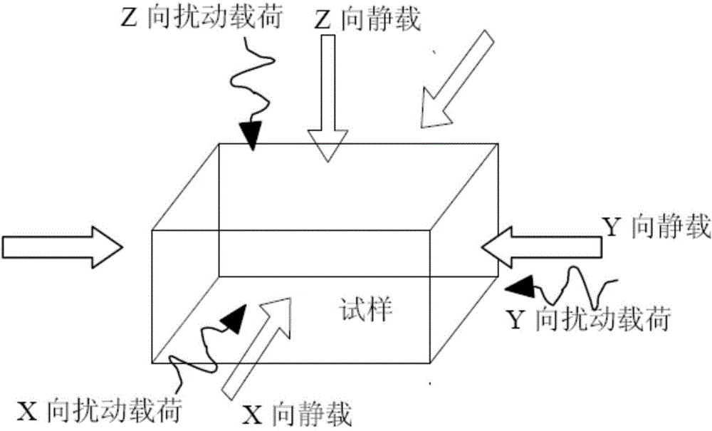
[0020] During the test, according to the size of the rock sample 7 to be tested, the positions of the loading splint 8 in the horizontal Y direction and the loading splint 10 in the horizontal X direction are adjusted, and the center of the rock sample 7 to be tested is aligned with the loading splint 8 in the horizontal Y direction and the loading splint 10 in the horizontal X direction. The center of the loading splint 10 is automatically adjusted by the computer according to the requirements of the experiment. The servo hydraulic system is applied to the three axial directions of the rock sample 7 by the servo hydraulic cylinders 9, 12, and 15. And it can realize the loading of curve loads such as half sine wave, triangular wave, square wave, etc., and realize the test effect of static load and dynamic disturbance load under the triaxial state. The static load-disturbance load schematic diagram of the tested rock sample 7 is as follows image 3 shown.

[0021] In the above ...


PUM


Abstract

The invention discloses impact disturbance surrounding rock testing equipment which comprises a top plate, a base, support standing columns, screw columns, a crossbeam, a crossbeam lifting motor and reducer part, a chain gear, an impact hammer, an impact hammer guide rod, a horizontal X-direction loading clamp plate, a horizontal Y-direction loading clamp plate, a horizontal X-direction servo hydraulic cylinder, a horizontal Y-direction servo hydraulic cylinder, a vertical Z-direction servo hydraulic cylinder, and an acceleration sensor. The impact disturbance surrounding rock testing equipment can apply static and dynamic loads to a large-size rock sample in three directions and apply certain waveform impact loads to the large-size rock samples along the vertical direction so as to simulate the disturbance response condition of the rock sample in a deep high stress environment.

Description

technical field [0001] The invention belongs to rock mechanics test equipment, in particular, relates to a test equipment for impact disturbance surrounding rock with impact disturbance function. Background technique [0002] In various engineering practices in nature, such as various mining projects, railway road tunnel construction, etc., when excavating deep high-stress rock mass, the rock mass must bear high static loads such as in-situ stress and structural stress, as well as The stress field change of the original rock or the influence of stress disturbance caused by the excavation of adjacent caverns, the action of dynamic loads such as excavation blasting operations or mechanical drilling, or the impact force caused by earthquakes and blasting. It should be noted that when the deep underground rock mass engineering structure is subjected to shock disturbances such as seismic waves and blasting shock waves, the damage caused by the dynamic instability of the rock mass...

Claims


Application Information

Patent Timeline
Patent Type & Authority Applications(China)
IPC IPC(8): G01N3/36
Inventor 王斌曾泽民赵伏军王卫军万文
Owner HUNAN UNIV OF SCI & TECH
Learn More