Air-ground amphibious vehicle
A vehicle, land and air technology, applied in the field of land and air amphibious vehicles, can solve problems such as endangering life safety, single structure, and no technical solution, and achieve the effect of prolonging service life and improving safety performance
- Summary
- Abstract
- Description
- Claims
- Application Information
AI Technical Summary
Problems solved by technology
Method used
Image
Examples
Embodiment 1
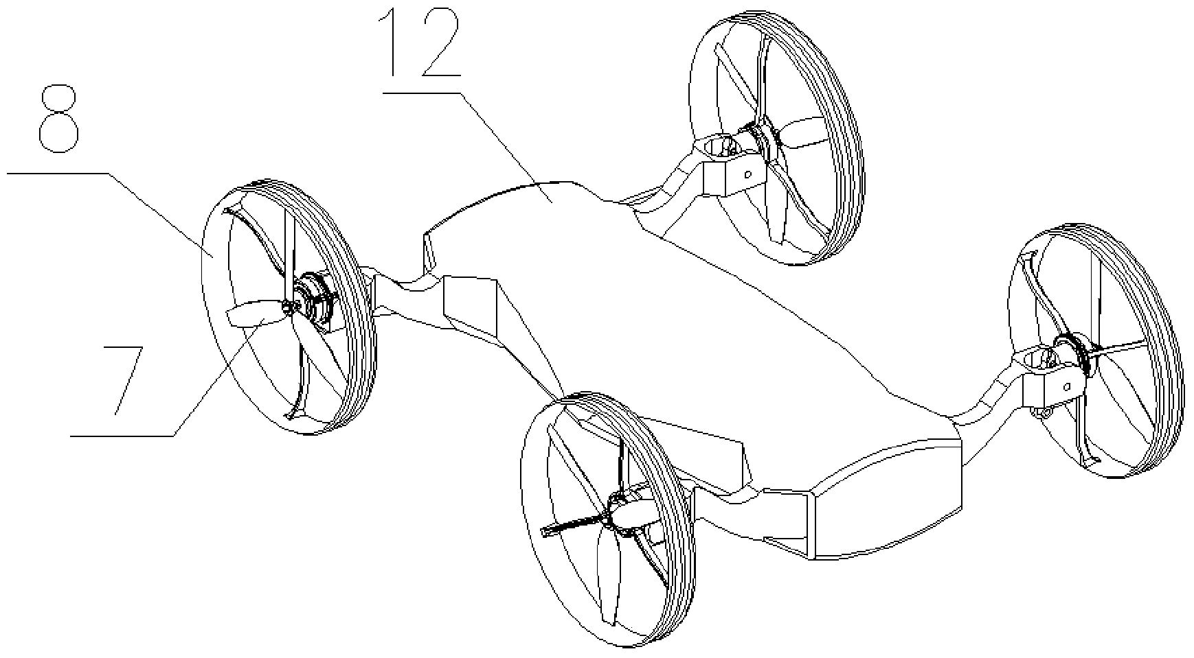
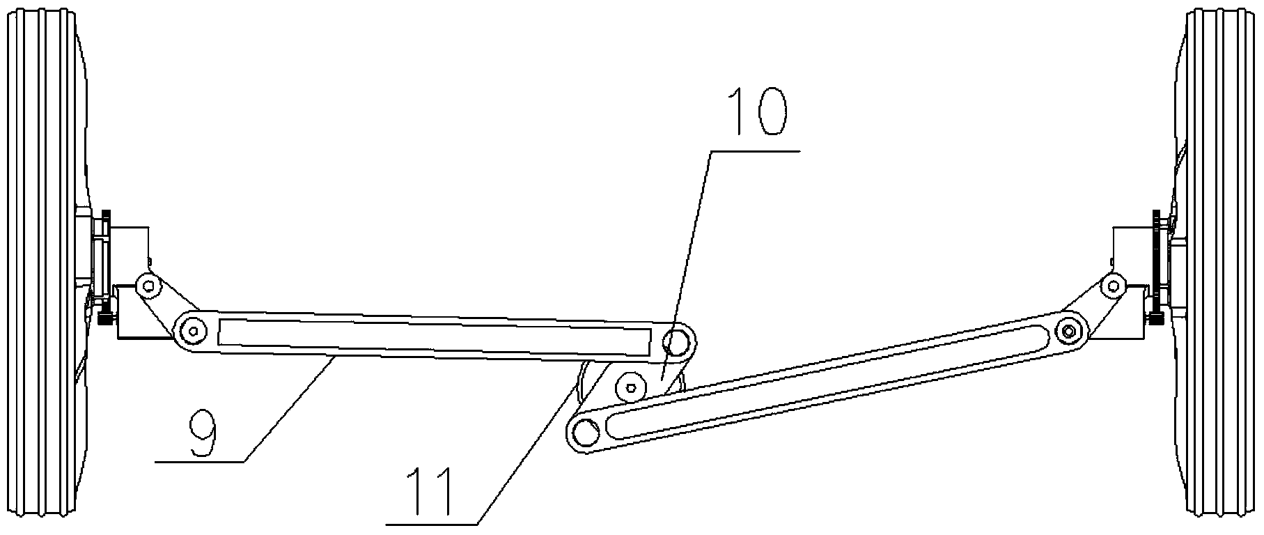
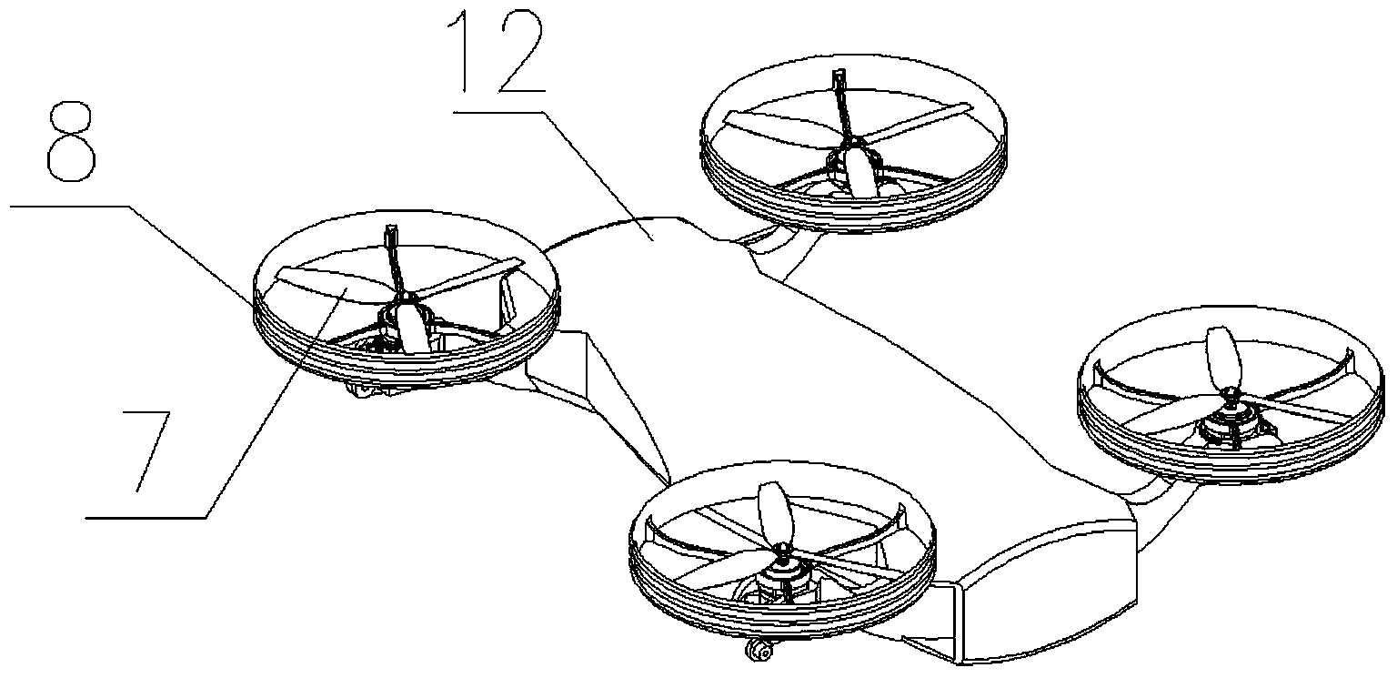
[0040] Such as Figure 1-6 As shown, a land-air amphibious vehicle includes a vehicle body base 12, a power mechanism, a transmission mechanism, and a drive assembly. The power of the power mechanism drives the drive assembly through the transmission mechanism, and the drive assembly is deformably arranged on the On the vehicle body base 12, it can fly in the air by overcoming air resistance and its own gravity or travel on the ground by overcoming ground friction.
[0041] The land-air amphibious vehicle also includes a control module and a communication module, the power mechanism includes a battery and a motor, the control module and the motor are electrically connected to the battery, and the communication module is used to establish the The communication link between the amphibious vehicle and the outside world. The communication module may include information collection equipment, information storage equipment, information sending device and information receiving device...
Embodiment 2
[0053] Such as Figure 7-8 As shown, compared with Embodiment 1, the difference of this embodiment is: a motor is installed on each of the wing assemblies, the motor is a high and low speed motor 13, and the flight propeller 7 and the hub 8 are the same. The shafts are fixedly connected, and each of the high and low speed motors 13 drives the flight propeller 7 and the hub 8 mounted on the wheel assembly of the high and low speed motors 13 to rotate simultaneously.
[0054] The flying propeller 7 and the hub 8 in this implementation are all synchronously rotating in the air flight state and the ground driving state. The rotating speeds of the high and low speed motors 13 are different under the above two states, and the high and low speed motors 13 are automatically controlled by manual or control modules to rotate at low speeds. Or high-speed rotation, select low-speed rotation when driving on the ground, and high-speed rotation when flying in the air.
Embodiment 3
[0056] Such as Figure 9 As shown, compared with Embodiment 1, the difference of this embodiment is that: a motor and a transmission mechanism are installed on each of the wheel wing assemblies, and the transmission mechanism includes a gearbox 14 and a clutch. The box 14 includes an input shaft and two output shafts, a driving gear 15 is installed on the input shaft, and a driven gear 16 is installed on the two output shafts, and the driven gears 16 are hub drive gears respectively 17 and flight propeller drive gear 18, the hub 8 is coaxially fixedly connected with a hub gear meshed with the hub drive gear 17, and the flight propeller 7 is coaxially fixedly connected with a hub gear meshed with the flight propeller drive gear 18 The flying propeller gear, the clutch is used to switch the engagement of the driving gear 15 on the input shaft with the hub driving gear 17 or the flying propeller driving gear 18.
[0057] The cockpit is provided with a clutch switch linked with t...
PUM
 Abstract
Description
Claims
Application Information
 - Generate Ideas
- Intellectual Property
- Life Sciences
- Materials
- Tech Scout
- Unparalleled Data Quality
- Higher Quality Content
- 60% Fewer Hallucinations
Browse by: Latest US Patents, China's latest patents, Technical Efficacy Thesaurus, Application Domain, Technology Topic, Popular Technical Reports.
© 2025 PatSnap. All rights reserved.Legal|Privacy policy|Modern Slavery Act Transparency Statement|Sitemap|About US| Contact US: help@patsnap.com


