
Electrode bar production method, electrode bar and fusion splicer comprising electrode bar

A production method and electrode rod technology, which is applied in the field of optical fiber fusion, can solve the problems of poor discharge effect of electrode rods, and achieve the effects of less replacement, less corrosion, and less difficult operation

Active Publication Date: 2015-02-18
INNO INSTR (CHINA) INC
View PDF5 Cites 0 Cited by
  • Summary
  • Abstract
  • Description
  • Claims
  • Application Information

AI Technical Summary

Problems solved by technology

[0005] The invention provides a method for making an electrode rod to solve the technical problem in the prior art that the electrode rod sticks to glass fibers during the discharge process, which leads to the deterioration of the discharge effect of the electrode rod and the need for frequent replacement.
[0006] The invention provides an electrode rod to solve the technical problem in the prior art that the electrode rod sticks to glass fiber during the discharge process, which leads to the deterioration of the discharge effect of the electrode rod and the need for frequent replacement.

Method used


Image

  • Electrode bar production method, electrode bar and fusion splicer comprising electrode bar
  • Electrode bar production method, electrode bar and fusion splicer comprising electrode bar
  • Electrode bar production method, electrode bar and fusion splicer comprising electrode bar

Examples


Embodiment Construction

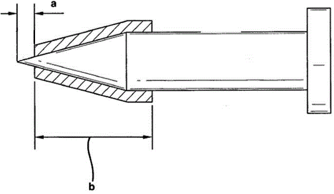
[0026] Due to the adhesion of glass fibers to the rear end of the existing electrode rods, the discharge effect will be affected after long-term use, resulting in the need to replace the electrode rods, resulting in frequent replacement of the electrode rods. In order to solve this problem, the Chinese patent application "201110000507.3" discloses "an electrode rod with an insulating coating and an optical fiber fusion splicer including the electrode rod". High-temperature insulating coating. The high-temperature insulating coating is generally made of insulating materials such as ceramics or silicon carbide. The high-temperature insulating coating is not coated on the top of the rod tip (discharge end), so that the tip of the rod tip (discharge end) is within the allowable conduction state. Although the above-mentioned technical solution solves the problem of glass fiber sticking on the electrode rod to a certain extent, its process has the following defects: the bonding mode...


PUM


Abstract

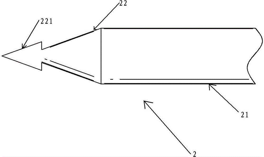
The invention discloses an electrode bar production method. The electrode bar production method mainly includes: producing an electrode bar blank, wherein the electrode bar blank at least comprises a discharge end blank with the perimeter of the outer side face larger than the discharge end of a finished electrode bar; then, subjecting the electrode bar blank to heat treatment so as to obtain an insulation oxide layer by in-situ synthesis; finally, processing the discharge end blank of the electrode bar blank so as to obtain the finished electrode bar. Meanwhile, the invention discloses the electrode bar. One insulation oxide layer obtained by in-situ synthesis is arranged on the outer surface of at least the tip of the electrode bar, and the insulation oxide layer is not arranged on the discharge end which is in an allowed conducting state. The electrode bar production method is low in operation difficulty; the insulation oxide layer of the electrode bar is arranged on the tip of the electrode bar by in-situ synthesis, so that the insulation oxide layer and a basal body are higher in binding force, proneness to coating shedding, instable discharge and the like is avoided, and the problem that the electrode bar needs to be replaced frequently due to the fact that the rear of the electrode bar close to the discharge end is contaminated by fiberglass easily is solved.

Description

technical field [0001] The invention relates to the technical field of optical fiber fusion, in particular to a method for manufacturing an electrode rod used in an optical fiber fusion splicer, the electrode rod, and an optical fiber fusion splicer including the electrode rod. Background technique [0002] Optical fiber fusion splicers are mainly used for the construction and maintenance of optical cables in optical communications. The general working principle is to use a high-voltage arc to melt the sections of the two optical fibers, and at the same time use a high-precision motion mechanism to gently advance the two optical fibers into one, so as to realize the coupling of the optical fiber mode field. Among them, optical fiber fusion is to perform high-voltage and high-frequency discharge on a pair of electrode rods to generate a high-temperature welding arc, thereby melting the end face of the optical fiber. [0003] When optical fiber is welded, the temperature of t...

Claims


Application Information

Patent Timeline
Patent Type & Authority Applications(China)
IPC IPC(8): G02B6/255
CPCG02B6/2551
Inventor 李楚元
Owner INNO INSTR (CHINA) INC
Learn More