
Channel type cooling structure of flame tube in combustion chamber of gas turbine

A cooling structure, gas turbine technology, applied in the direction of combustion chamber, continuous combustion chamber, combustion method, etc., can solve the problems of uneven temperature distribution on the wall surface of the flame tube, easy to cause large thermal stress, uneven heat load, etc., to improve cooling Efficiency, improved flow conditions, improved uniformity

Inactive Publication Date: 2015-02-18
BEIJING HUAQING GAS TURBINE & INTEGRATED GASIFICATION COMBINED CYCLE ENG TECH
View PDF7 Cites 7 Cited by
  • Summary
  • Abstract
  • Description
  • Claims
  • Application Information

AI Technical Summary

Problems solved by technology

[0005] On the one hand, the long-term operation of the flame tube at high temperature is faced with creep and oxidation problems, and it is subjected to thermomechanical fatigue during the continuous start-up and shutdown of the gas turbine; on the other hand, due to the uncertainty of the combustion field in the flame tube, resulting in The inhomogeneity of the heat load and the limitation of the cooling performance of the traditional cooling structure lead to the uneven temperature distribution on the wall of the flame tube itself, which is easy to cause large thermal stress

Method used


Image

  • Channel type cooling structure of flame tube in combustion chamber of gas turbine
  • Channel type cooling structure of flame tube in combustion chamber of gas turbine
  • Channel type cooling structure of flame tube in combustion chamber of gas turbine

Examples


Embodiment Construction

[0018] The principle, structure and specific implementation of the present invention will be further described in detail below in conjunction with the accompanying drawings and embodiments.

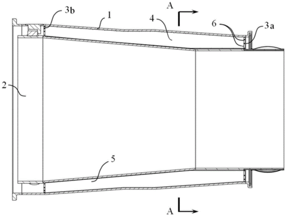
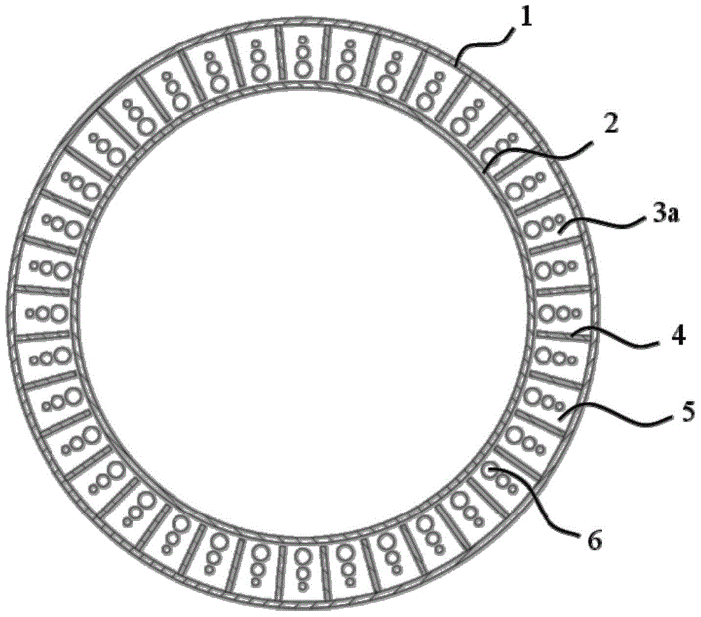
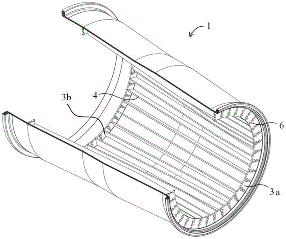
[0019] figure 1 It is a cross-sectional view of a gas turbine combustor flame tube with a channel cooling structure. As shown in the figure, a flow guide bushing 1 is arranged outside the flame tube 2, and the gap between the flow guide bush 1 and the flame tube 2 is An annular return air channel 5 is formed. The cooling structure is arranged in the annular return air passage 5, and the structure includes a plurality of baffles 4 arranged axially along the flame tube 2, a front end cover 3a and a rear end cover 3b; the baffles 4 are fixed on the guide bushing 1, the front end cover plate 3a is fixed on the inner wall of the guide bush 1 at the entrance of the annular return air channel 5, and the rear end cover plate 3b is fixed on the inner wall of the guide bush 1 at the outlet of the ...


PUM


Abstract

The invention discloses a channel type cooling structure of a flame tube in a combustion chamber of a gas turbine and belongs to the technical field of gas turbines. The cooling structure comprises a plurality of separation plates which are arranged in the axial direction of the flame tube, a front end cover plate and a rear end cover plate, wherein the separation plates are fixed on the inner wall of a diversion lining; the front end cover late is fixed on the inner wall of the diversion lining at the inlet of a ring-shaped return air channel; the rear end cover plate is fixed on the inner wall of the diversion lining at the outlet of the ring-shaped return air channel; a plurality of flow limiting holes are formed in the front end cover plate and the rear end cover plate. The ring-shaped return air channel is internally provided with a plurality of separation plates, so that the ring-shaped return air channel is divided into a plurality of axial cooling channels and the return air can flow in the axial cooling channels so as to reduce the tangential speed of the air, improve the flowing condition, bring benefit to enhance the convective heat transfer coefficient, improve the cooling efficiency, improve the uniformity of the air entering into the flame tube, improve the flowing condition in the flame tube and bring benefit to texture combustion.

Description

technical field [0001] The invention relates to the technical field of gas turbines, in particular to a cooling structure for a combustion chamber flame cylinder of a gas turbine. Background technique [0002] A gas turbine consists of three major components: a compressor, a combustor, and a turbine. Among them, the highest temperature zone of the gas turbine exists in the combustion chamber, which is used as a gas combustion component connecting the compressor and the turbine, converts chemical energy into heat energy, and passes hot air into the turbine to perform work. A fuel nozzle is installed at the front end of the combustion chamber. The fuel ejected from the nozzle and the incoming air are combusted in the combustion chamber. The combustion temperature can reach more than 2000 degrees Celsius and the pressure can reach 20 atmospheres. It is difficult for the outer cylinder of the combustion chamber to withstand such high pressure at high temperature. In order to r...

Claims


Application Information

Patent Timeline
IPC IPC(8): F23R3/42
Inventor 查筱晨刘小龙张珊珊张龙
Owner BEIJING HUAQING GAS TURBINE & INTEGRATED GASIFICATION COMBINED CYCLE ENG TECH
Learn More