
Compressor apparatus with bleed slot including turning vanes

A discharge tank and compressor technology, applied in the field of compressors, can solve problems such as unfavorable structure and thermomechanical effects of compressors

Active Publication Date: 2018-11-13
GENERAL ELECTRIC CO
View PDF15 Cites 0 Cited by
  • Summary
  • Abstract
  • Description
  • Claims
  • Application Information

AI Technical Summary

Problems solved by technology

However, pressure losses in the discharge system can drive the need to use air from higher stages than required
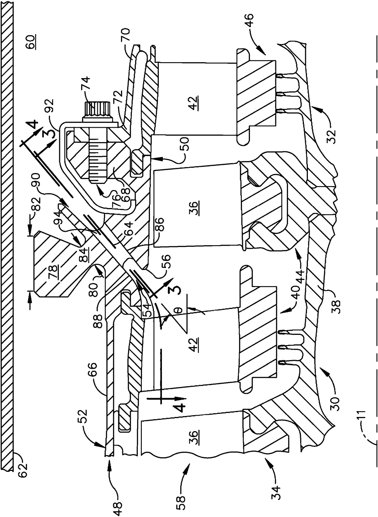
[0006] Another problem with bleed air extraction is that the configuration of bleed air slots for optimal aerodynamic efficiency can cause adverse structural and thermomechanical effects on the compressor

Method used


Image

  • Compressor apparatus with bleed slot including turning vanes
  • Compressor apparatus with bleed slot including turning vanes
  • Compressor apparatus with bleed slot including turning vanes

Examples


Embodiment Construction

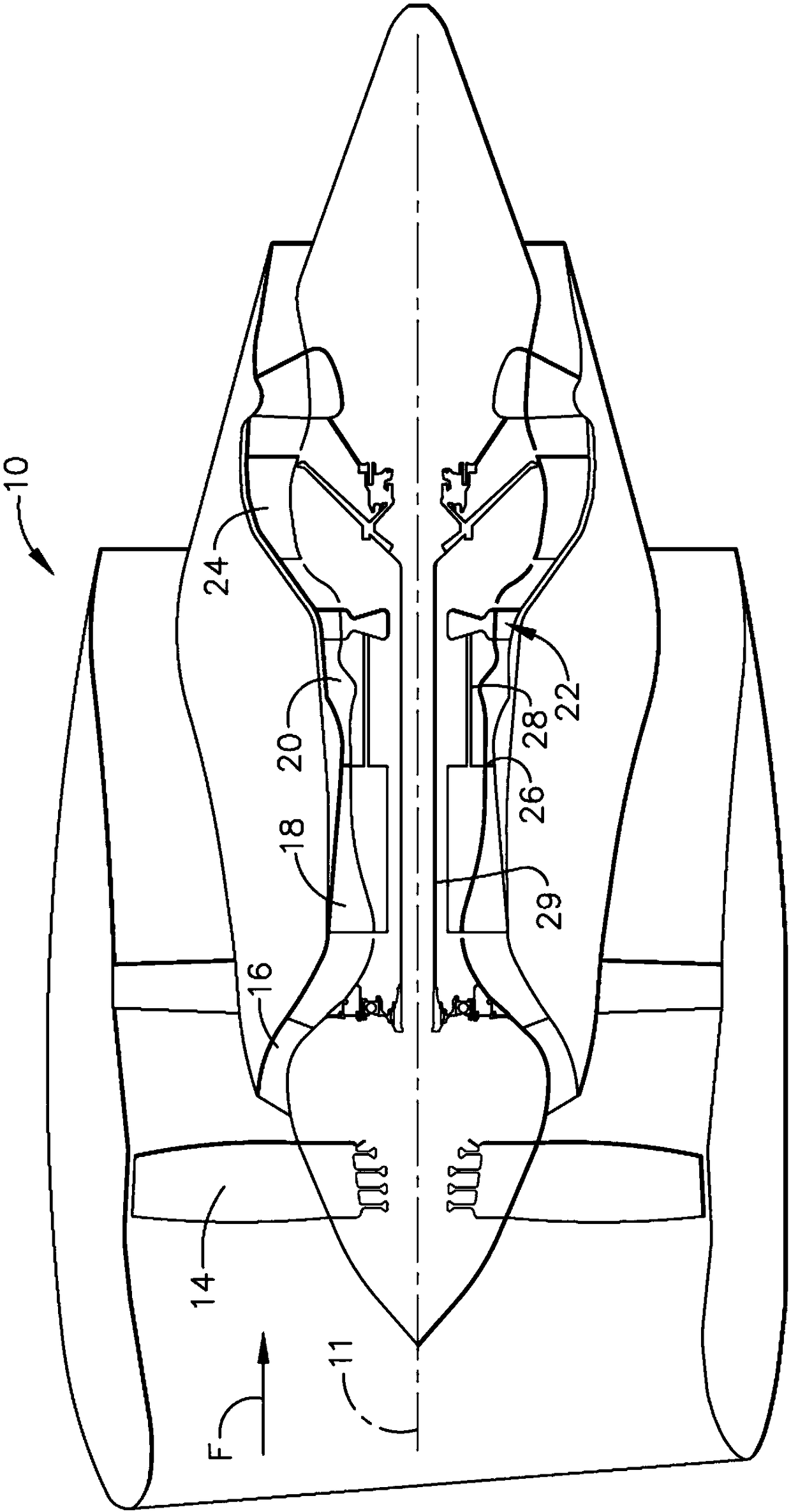
[0036] With reference to the drawings in which like reference numerals denote like elements in the various views, figure 1 An exemplary gas turbine engine 10 is depicted. Although the illustrated example is a high-bypass turbofan engine, the principles of the invention are applicable to other types of engines, such as low-bypass turbofans, turbojets, turboprops, etc., and with any number of compressors Turbine engine with turbine shaft. Engine 10 has a longitudinal centerline or axis 11 .

[0037] It should be noted that, as used in this specification, the terms "axial" and "longitudinal" both refer to directions parallel to the centerline axis 11, while "radial" refers to directions perpendicular to the axial direction, and "tangential " or "circumferential" refers to directions perpendicular to each other in the axial and radial directions. As used in this specification, the term "forward" or "front" refers to a position relatively upstream in the airflow through or aroun...


PUM


Abstract

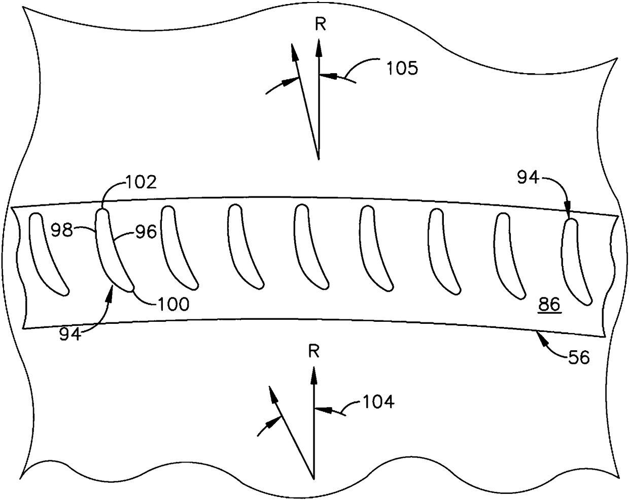
A compressor bleed slot apparatus includes: an annular compressor casing; a stator vane row including a plurality of stator vanes disposed inside the compressor casing; a blade row mounted for rotation about a centerline axis inside the compressor casing, axially downstream of the stator row; a bleed slot passing through the compressor casing, the bleed slot having an inlet and an outlet and extending along a slot axis, wherein the bleed slot is bounded by inboard and outboard walls defined within the compressor casing, the inboard and outboard walls diverging from each other in a downstream direction relative to the bleed slot; and a plurality of turning vanes disposed in the slot, the turning vanes configured to reduce a tangential velocity of airflow through the bleed slot. The application also provides a gas turbine engine apparatus.

Description

technical field [0001] The present invention relates generally to compressors in gas turbine engines, and more particularly to discharge slots in such compressors. Background technique [0002] In fluid flow order, a gas turbine engine includes, in sequence, a compressor, a combustor, and a turbine in fluid communication. The turbine is mechanically connected to the compressor and the three components define a turbine core. The core is operable in a known manner to generate a flow of hot pressurized combustion gases to operate the engine and to perform useful work, such as providing propulsion thrust or mechanical work. [0003] In at least some known gas turbine engines, a portion of the high pressure air is extracted or extracted from the compressor for other uses, such as for turbine cooling, pressurized bearing sumps, purge air, or aircraft environmental control. This "bleed air" is drained from the compressor using a drain slot located in a particular section or stage...

Claims


Application Information

Patent Timeline
Patent Type & Authority Applications(China)
IPC IPC(8): F04D29/42F04D29/44F02C3/06
CPCF02C3/06F04D29/4206F04D29/441F05D2220/3216F02C6/08F04D29/542F05D2240/128F04D27/009F05D2220/32F02C3/04
Inventor C.W.梅克尔M.F.亚当R.K.塞尔梅尔M.A.托马斯S.M.泰勒A.斯特雷特
Owner GENERAL ELECTRIC CO
Learn More