
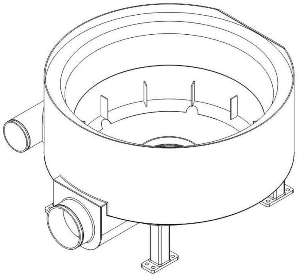
Mixing tank structure of fracturing blender truck

A technology for mixing tanks and sand mixers, which is applied in the direction of mixer accessories, mixers, dissolving, etc. It can solve problems such as excessive vortex, discharge centrifugal pump impact, and large discharge pressure fluctuations, so as to promote stability, relieve kinetic energy, The effect of reducing kinetic energy

Inactive Publication Date: 2020-10-09
SICHUAN HONGHUA PETROLEUM EQUIP
View PDF6 Cites 2 Cited by
  • Summary
  • Abstract
  • Description
  • Claims
  • Application Information

AI Technical Summary

Problems solved by technology

The current sand mixing truck (skid) sand mixing tank has excessive vortex, excessive splash, more gas content, poor mixing effect, large impact on the discharge centrifugal pump, large discharge pressure fluctuations, and long service life of the equipment. Short and other questions

Method used


Image

  • Mixing tank structure of fracturing blender truck
  • Mixing tank structure of fracturing blender truck
  • Mixing tank structure of fracturing blender truck

Examples


Embodiment 1

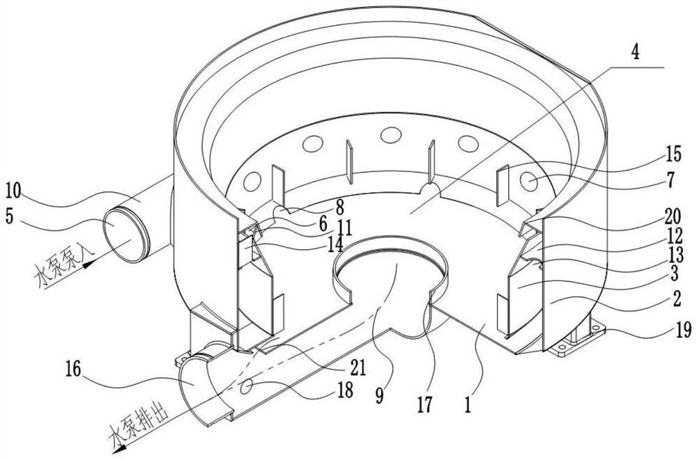
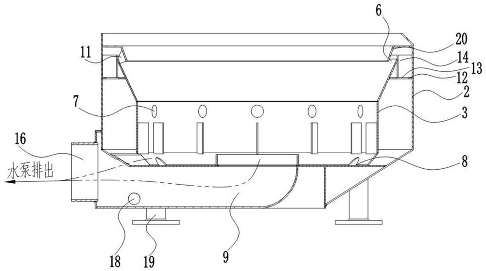
[0036] A mixing tank structure of a sand mixer, such as Figure 1 to Figure 5 As shown, a tank body is included, the tank body includes a tank bottom plate 1 and a tank inner layer 3 and a tank outer layer 2 arranged on the tank bottom plate, the tank bottom plate 1 and the tank inner layer 3 form a stirring cavity 4, There is a gap between the tank inner layer 3 and the tank outer layer 2 to form a tank layer gap, the tank outer layer is provided with a liquid inlet 5, the tank inner layer is provided with a liquid outlet, and the liquid inlet The mouth, the gap between the tank layers and the liquid outlet are connected to form a liquid inlet channel. The bottom of the tank body is also provided with a liquid discharge channel, through which the liquid is introduced into the tank, and then discharged through the liquid discharge channel.

[0037] In this embodiment, in the design of the whole structure, the figure 2 It is an illustration of the flow direction of the liquid...

Embodiment 2

[0056] On the basis of the above-mentioned embodiment 1, the design of the liquid outlet not only adopts the above three fixed (upper, middle, lower) design methods, but the main purpose of the design of the liquid outlet is to introduce liquid into the tank , and in the design of this structure, in this embodiment, as follows:

[0057] Based on the design of the above specific structure, as a further optimized design, the liquid outlet includes the upper liquid outlet 6 and the middle liquid outlet 7, or the liquid outlet includes the upper liquid outlet 6 and the lower liquid outlet port 8, or, the liquid outlet includes middle liquid outlet 7 and lower liquid outlet 8;

[0058] Wherein, the upper liquid outlet 6 is also provided with an upper water baffle 20, and the upper liquid outlet 6 is formed with the water baffle 15, the tank inner layer 3 and the tank outer layer 2 as side walls, or, the The upper liquid outlet 6 is a plurality of liquid outlets opened on the upper...

Embodiment 3

[0063] Similar to Example 2, but on the basis of the above, the design of the liquid outlet can be one of them. Specifically, based on the design of the above-mentioned specific structure, as a further optimized design, the liquid outlet includes the above Liquid outlet 6 or middle liquid outlet 7 or lower liquid outlet 8;

[0064] Wherein, the upper liquid outlet 6 is also provided with an upper water baffle 20, and the upper liquid outlet 6 is formed with the water baffle 15, the tank inner layer 3 and the tank outer layer 2 as side walls, or, the The upper liquid outlet 6 is a plurality of liquid outlets opened on the upper part of the inner layer 3 of the tank;

[0065] The middle liquid outlet 7 is a plurality of liquid outlets opened in the middle of the inner layer of the tank;

[0066] The lower liquid outlet 8 is a plurality of liquid outlets opened in the lower part of the inner layer of the tank.


PUM


Abstract

The invention discloses a sand mixing tank of oil field fracturing corollary equipment, particularly relates to a stirring tank structure of a sand mixing truck, and belongs to the field of oil fieldcorollary equipment. The structure comprises a tank body, wherein the tank body comprises a tank bottom plate, and a tank inner layer and a tank outer layer which are arranged on the tank bottom plate; wherein a stirring containing cavity is formed by the tank bottom plate and the tank inner layer, a gap exists between the tank inner layer and the tank outer layer to form a tank layer gap, a liquid inlet is formed in the tank outer layer, liquid is introduced into the tank body through a liquid inlet channel, and then the liquid is discharged through a liquid discharging channel. According tothe invention, the problems that a traditional stirring tank is too large in vortex, too large in splashing and high in gas content are solved, and the problems of poor mixing effect, large impact ona discharge centrifugal pump, large discharge pressure fluctuation, short service life of equipment and the like in the prior art are solved, large impact force generated on the side wall of a tank body when liquid enters the tank body is effectively reduced through the structure, and meanwhile, kinetic energy of the liquid is effectively relieved through the structure, and the overall stability of the liquid after entering the tank body is promoted.

Description

technical field [0001] The invention relates to a sand mixing tank of oil field fracturing supporting equipment, in particular to a mixing tank structure of a sand mixing vehicle, which belongs to the field of oil field supporting equipment. Background technique [0002] As the core component of the sand mixing vehicle (skid), the sand mixing tank is mainly used to stir and mix the liquid added to the sand mixing tank, proppant and other chemical additives in a short period of time to form a uniform mixed fracturing fluid and then discharge it. Uniform, exhaust gas is beneficial to reduce the impact and erosion on the discharge centrifugal pump, improve the stability of discharge pressure fluctuations and the life of the centrifugal pump. The current sand mixing truck (skid) sand mixing tank has excessive vortex, excessive splash, more gas content, poor mixing effect, large impact on the discharge centrifugal pump, large discharge pressure fluctuations, and long service life...

Claims


Application Information

Patent Timeline
Patent Type & Authority Applications(China)
IPC IPC(8): B01F15/00B01F15/02
CPCB01F35/52B01F35/5312B01F35/531B01F35/712
Inventor 弋大浪李泓杉李水华刘波
Owner SICHUAN HONGHUA PETROLEUM EQUIP
Learn More