
Rapid stripping device, stripping equipment and stripping method for metal layer of cathode plate

A stripping device and cathode plate technology, applied in the direction of electrolysis process, electrolysis components, etc., can solve the problems that there is no public solution to technical problems, can not be solved, and achieve the effect of improving reliability, rapid stripping, and reducing failure factors

Active Publication Date: 2016-09-07
株洲优瑞科有色装备有限公司
View PDF8 Cites 2 Cited by
  • Summary
  • Abstract
  • Description
  • Claims
  • Application Information

AI Technical Summary

Problems solved by technology

[0005] The stripping equipment in the above-mentioned patent documents does not disclose the solution to the above-mentioned technical problems, so it cannot solve the above-mentioned problems

Method used


Image

  • Rapid stripping device, stripping equipment and stripping method for metal layer of cathode plate
  • Rapid stripping device, stripping equipment and stripping method for metal layer of cathode plate
  • Rapid stripping device, stripping equipment and stripping method for metal layer of cathode plate

Examples


Embodiment 1

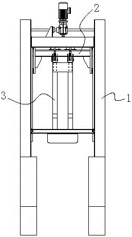
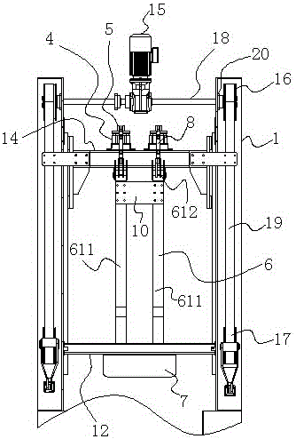
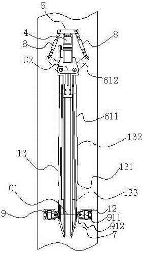
[0041] Embodiment 1: as Figure 1 to Figure 4 As shown, a quick peeling device for the metal layer of the cathode plate includes a frame 1, a lifting mechanism 2 arranged on the top of the frame 1 and a peeling mechanism 3 arranged on the lifting mechanism 2, the peeling The mechanism 3 includes a cylinder energy storage unit 4 arranged on the lifting mechanism 2, the gas of the cylinder energy storage unit is in a pre-compressed state, connected with the cylinder energy storage unit 4 and can store energy in the cylinder Under the action of the unit, the lifting fork seat 5 reciprocating up and down, the stripping knife opening and closing frame 6 on both sides, and the stripping knife 7 arranged on the stripping knife opening and closing frame 6; the stripping knife opening and closing frame 6 includes The long arm 611 and the short arm 612 with one end obliquely fixedly connected to one end of the long arm 611 are hinged to the lifting mechanism 2 at the junction of the lon...

Embodiment 2

[0060] Embodiment 2: as Figure 9 As shown, compared with Embodiment 1, the difference of this embodiment is that the peeling mechanism is arranged on the lifting mechanism as a compression spring energy storage unit, and the compression spring energy storage unit includes a The sleeve 26 on the upper part of the lifting beam 14, the compression spring 27 arranged inside the sleeve 26 and the piston 28 with a rod; the piston 28 is in contact with the compression spring 27, and the rod of the piston 28 passes through One end of the sleeve 26 is connected with the lifting fork 5 . When the lifting fork 5 moves downward, the compression spring 27 is compressed, and the energy is stored through the compression spring 27; when the lifting fork 5 moves upward, the compression spring 27 is reset and rebounded, and the energy is released through the lifting fork 5 Going out, such a cycle forms a process in which the compression spring energy storage unit repeatedly stores energy and ...

Embodiment 3

[0061] Embodiment 3: as Figure 10 to Figure 12 As shown, compared with Embodiment 1 or Embodiment 2, the difference is that a cathode plate locking device 29 is also provided at the bottom of the frame 1 of the quick stripping device, which includes locking plates 291 on both sides, The locking plate support bar 292 on both sides, the locking plate cylinder or the locking plate hydraulic cylinder 293 on both sides; one end of the locking plate support bar 292 on each side is hinged with the bottom of the frame 1, and the other end is connected with each side The outer surface of locking plate 291 is hinged, and one end of locking plate cylinder or locking plate hydraulic cylinder 293 on each side is hinged with the bottom of the frame 1, and its other end is hinged with the outer surface of each side locking plate 291, so The locking plates 291 on both sides are relatively symmetrically arranged, and the inner surfaces of the locking plates 291 on both sides include two strai...


PUM


Abstract

The invention discloses a rapid stripping device, stripping equipment and a stripping method for a negative plate metal layer. The rapid stripping device comprises a rack, a lifting mechanism and a stripping mechanism, wherein the stripping mechanism comprises a cylinder energy storage unit or a compressed spring energy storage unit; gases or compressed springs in the cylinder energy storage unit or the compressed spring energy storage unit are positioned in lifting forked seats, stripping knife opening / closing racks on two sides and stripping knives in pre-compressed states; the stripping knife opening / closing racks comprise long arm pieces and short arm pieces; the stripping knife opening / closing racks on two sides are respectively hinged to two sides of the lifting mechanism; the short arm pieces on two sides are respectively hinged with one ends of connecting rods on two sides; the other ends of the connecting rods on two sides are respectively hinged to the lifting forked seats. The rapid stripping device also comprises limiting wheel devices on two sides, wherein the long arm pieces on two sides are slope-shaped; the limiting wheels on two sides are respectively contacted with the slope-shaped surfaces of the long arm pieces on two sides; and the circle center distance between the limiting wheels on two sides is larger than the circle center distance between the hinged pieces of the stripping knife opening / closing racks on two sides with the two sides of the lifting mechanism. According to the rapid stripping device disclosed by the invention, the stripping speed and working efficiency can be improved.

Description

technical field [0001] The invention relates to a rapid stripping technology for stripping the electrodeposited (or electrolytic) metal layer on the cathode plate, in particular to a rapid stripping device, stripping equipment and stripping method for the metal layer on the cathode plate, which belongs to the non-ferrous metallurgy industry. legal smelting technology field. Background technique [0002] In the field of hydrometallurgy in the non-ferrous smelting industry, non-ferrous metals are obtained by first attaching the non-ferrous metals to the surface of the cathode plate to form a metal layer through electrolysis and electrowinning, and then peeling off the metal layer from the surface of the cathode plate. . According to the current production process, there are two methods for stripping the non-ferrous metal layer from the cathode plate, one is manual stripping, and the other is machine stripping. Using machine stripping is faster and more efficient than manual ...

Claims


Application Information

Patent Timeline
Patent Type & Authority Patents(China)
IPC IPC(8): C25C7/08
Inventor 周米可王勇刚江征宇王锦鸿何纯海刘文虎张文强
Owner 株洲优瑞科有色装备有限公司
Learn More