
Conductive road sign paint and conductive, magnetic and driving type electromagnetic tire

A conductive and conductive technology, applied in circuits, conductive coatings, road signs, etc., can solve the problems of microwave damage efficiency to human body, low charging efficiency, complicated construction, etc., and achieve simple and convenient laying and construction, high charging and transmission efficiency, The effect of cruising range extension

Inactive Publication Date: 2015-02-18
刘跃进
View PDF1 Cites 5 Cited by
  • Summary
  • Abstract
  • Description
  • Claims
  • Application Information

AI Technical Summary

Problems solved by technology

The three technologies have their own advantages and disadvantages. The energy transmission distance of microwave technology is relatively long. However, high-power microwave has certain damage to the human body and the efficiency is relatively low, so it is not considered to be used in the field of civilian electric vehicles; electromagnetic resonance technology The energy transmission distance can reach tens of centimeters, but the transmission power is relatively not as large as that of electromagnetic coupling technology; electromagnetic coupling technology is more suitable for high-power energy transmission, but the environment used is close distance: the distance between the charging transmitter and the receiver The distance is less than tens of millimeters
[0005] However, the direct use of the existing wireless charging technology in the field of high-power electric vehicle charging will generate certain electromagnetic radiation, and there are still problems such as relatively complicated construction and relatively high cost.
To sum up, the disadvantages and deficiencies of the existing wireless charging technology include: 1. The construction is complicated and the installation and construction costs are high; 2. The charging efficiency is relatively low; 3. There is a certain amount of electromagnetic radiation

Method used


Image

  • Conductive road sign paint and conductive, magnetic and driving type electromagnetic tire
  • Conductive road sign paint and conductive, magnetic and driving type electromagnetic tire
  • Conductive road sign paint and conductive, magnetic and driving type electromagnetic tire

Examples


Embodiment Construction

[0020] The present invention will be described in detail below in conjunction with the accompanying drawings and practical examples.

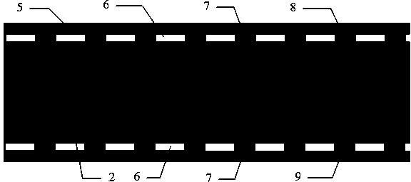
[0021] figure 1 Schematic diagram showing the low-voltage conductive charging belt (mobile charging belt) (8, 9) sprayed on the roadway (5) on the road, the driving lane is located in the middle of the roadway indicator line (6), and the mobile charging belt (8, 9) Spray on the wheel contact areas on the left and right sides of the roadway respectively, and the distance D (2) in the middle is generally not less than 50 cm; the specific spraying method and process are: 1. Clean the road surface (5); 2. Clean the road surface (5) on the road surface Spray two layers of insulating road marking paint or road marking paint (7) with a width of 30-150 cm on the parts where the left and right wheels often contact; 3. After the insulating road marking paint or road marking paint (7) is dry, spray 20- 140 centimeters of conductive road marking paint or...


PUM


Abstract

The invention discloses a pavement marked line coating with conductivity, a pavement marked line coating with insulating property, a method for spraying a low-voltage conductive type charging belt by the conductive and insulating pavement marked line coatings and a conductive, magnetic, rechargeable and driving type electromagnetic tire. The invention also discloses a mobile charging belt system for supporting charging during running of an electric automobile. The system comprises the low-voltage conductive type charging belt sprayed by conductive road sign paint or the pavement marked line coating, a conductive type tire (or a conductive type rechargeable tire), a current transducer, a charging belt controller, a charging controller (or a charging control receiver), a charging management background and an IC (integrated chip) charging card.

Description

technical field [0001] The invention discloses a conductive road marking paint or road marking paint, a conductive, magnetically permeable, rechargeable and drivable electromagnetic tire, and a road marking paint with conductive performance, an electromagnetic tire, and a charging belt controller. A mobile charging system that supports the charging of an electric vehicle while driving or stopping, consisting of a charging controller and a charging management background, belongs to the field of new energy vehicles. Background technique [0002] With the development of electric vehicle technology, the charging problem of electric vehicles will become increasingly prominent, and even become the throat that restricts the popularization and promotion of electric vehicles. Charging piles can solve the problem of charging electric vehicles while parked, but because the charging time is relatively long, it takes 6-8 hours for a general charging pile to fully charge the battery of an...

Claims


Application Information

Patent Timeline
IPC IPC(8): C09D5/24C09D5/25C09D5/00E01C7/35E01F9/04B60C19/08E01F9/00E01F9/506E01F9/518
CPCC08K3/04C08K3/08C08K2003/0806C08K2003/0812C08K2003/085C08K2201/001C08K2201/014C09D5/24H01B3/308
Inventor 刘跃进
Owner 刘跃进
Learn More