Spotting drill bushing

A technology of drill sleeves and positioning grooves, which is applied in the direction of drilling templates for workpieces, etc., which can solve the problems of unstable positioning and complex structures of drill sleeves, and achieve the effects of simple structure, large contact area, and stable positioning

Inactive Publication Date: 2015-02-18
CHONGQING UNION MACHINE MFG
View PDF0 Cites 0 Cited by
  • Summary
  • Abstract
  • Description
  • Claims
  • Application Information

AI Technical Summary

Problems solved by technology

[0003] The invention provides a positioning drill sleeve to solve the problem of unstable positioning and complicated structure of the existing drill sleeve

Method used


Image

  • Spotting drill bushing
  • Spotting drill bushing
  • Spotting drill bushing

Examples


Embodiment Construction

[0013] The present invention will be described in further detail below by means of specific embodiments:

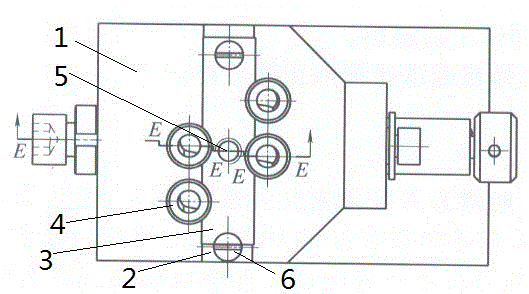
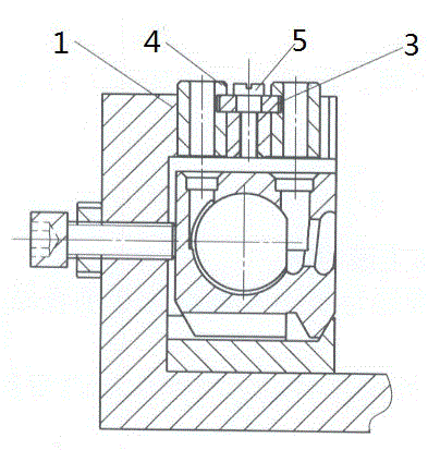
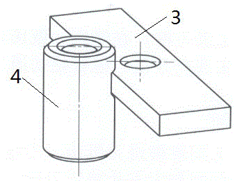
[0014] The reference numerals in the accompanying drawings of the description include: a drill template 1 , a through slot 2 , a flashboard 3 , a drill sleeve 4 , a first locking screw 5 and a second locking screw 6 .

[0015] Examples are attached Figure 1~3 As shown, in this embodiment, the drill sleeve is positioned, and a through groove 2 is opened on the top of the drill template 1. The through groove 2 is a stepped groove with a limiting bottom groove, and the inserting plate 3 is placed in the limiting bottom groove. The flashing plate 3 has the function of positioning, preventing the flashing plate 3 from moving horizontally.

[0016] The middle part of the flashboard 3 is fixed to the drill template 1 by the first locking screw 5, and the two ends of the flashboard 3 are fixed to the drill template 1 by two second locking screws 6.

[0017] Four vertical drill...


PUM


Abstract

The invention application discloses a spotting drill bushing, which aims at solving the problems that the existing drill bushing is not stable in spotting and comparatively complicated in structure. The spotting drill bushing comprises a drill plate; a straight slot is formed in the upper part of the drill plate; a spile is arranged in the straight slot; the middle part of the spile is fixed to the drill plate through a first locking screw; a plurality of vertical drill bushings are respectively arranged at positions, located at two sides of the spile, on the drill plate; a spotting slot is formed in the excircle of each drill bushing; two opposite side edges of the spile are inserted into the spotting slots to perform spotting on the drill bushings; when the drill bushing is used, guide spotting can be realized by inserting a drill bit, an expanding drill or a reamer into the drill bushing. 1, by adopting a mode that spotting is performed on the drill bushing by matching the spile and the spotting slot in the excircle of the drill bushing, the contact area between the spile and the excircle of the drill bushing is bigger and spotting is more stable in comparison with screw spotting; 2, the spotting can be realized on the multiple drill bushings only by one spile, and the structure is simpler.

Description

technical field [0001] The invention relates to a device for providing guidance for a drill bit in a boring machine or a drilling machine, in particular to a positioning drill sleeve. Background technique [0002] The function of the drill sleeve is to determine the axis position of the fixed-size tool such as the drill bit, reamer or reamer, and then guide the tool to process and improve the precision of the process. The drill sleeve is installed on the drill template, and the existing positioning method of the drill sleeve is: milling a notch on the outer circle of the drill sleeve, positioning and pressing the drill sleeve by screws perpendicular to the drill sleeve. The problems of this positioning method of the drill sleeve are: 1. The positioning is unstable; 2. If multiple drill sleeves are arranged on the drill template, each drill sleeve needs at least one screw for positioning, and the structure is more complicated. Contents of the invention [0003] The inventi...

Claims


Application Information

Patent Timeline
IPC IPC(8): B23B47/28
CPCB23B47/28
Inventor 邓雪峰
Owner CHONGQING UNION MACHINE MFG
Why Eureka
Try Eureka