
Feeding and unloading device for anti-jump bottle cap molding machine

A molding machine and bottle cap technology, which is applied to household components, household appliances, other household appliances, etc., can solve the problems of increasing equipment costs, falling, and inability to ensure that all rubber materials are blown off, and achieves easy installation and removal. Maintenance , the effect of saving production costs

Active Publication Date: 2016-09-28
SHAOXING HUANGGUAN MACHINERY
View PDF6 Cites 0 Cited by
  • Summary
  • Abstract
  • Description
  • Claims
  • Application Information

AI Technical Summary

Problems solved by technology

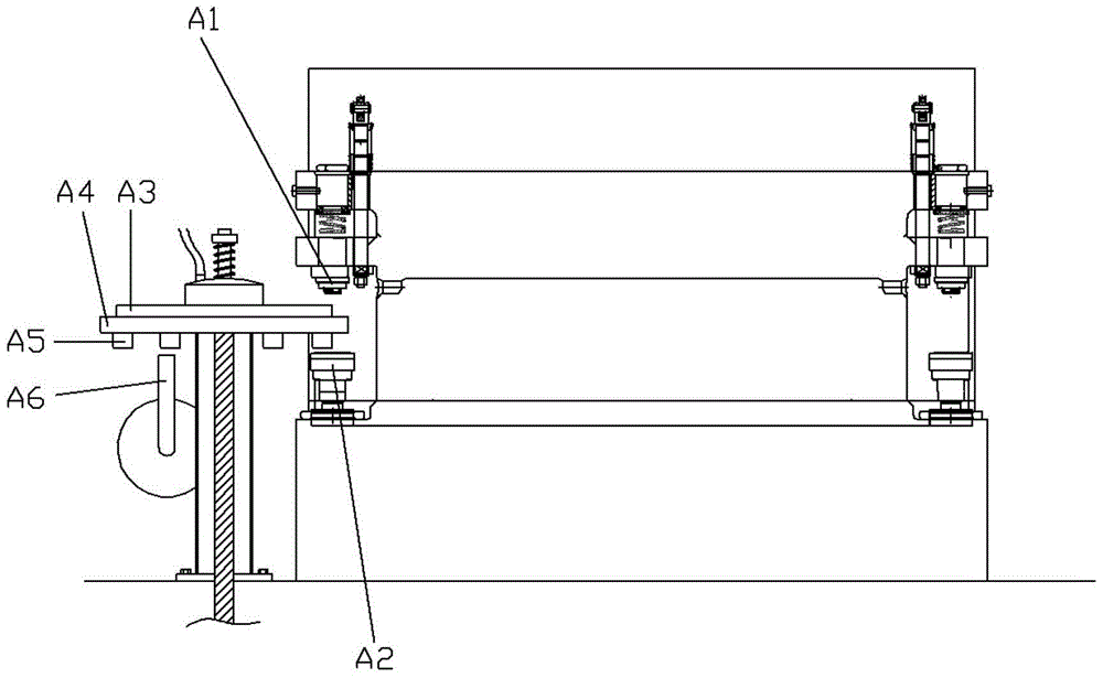
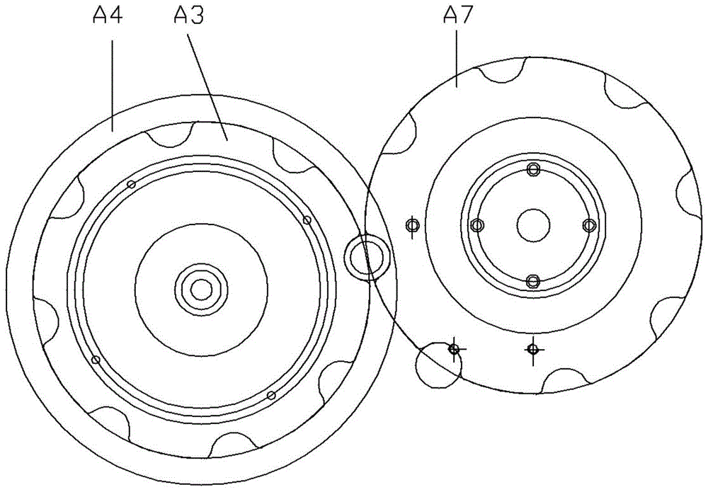
Its shortcomings are: 1. When the bottle cap is removed from the upper mold A1 to the feeding tray A4, the bottle cap has a small drop, and the bottle cap that falls on the feeding tray A4 will have a small upward movement. This jump will prevent all the bottle caps after demoulding from falling to the correct position of the lower cover plate A3, or even jump off the feeding plate A4, so during the process of bottle cap blanking, the demoulding is not in the correct position The finished bottle cap is easily dropped between the upper mold and the lower mold of the bottle cap molding machine by the cap delivery plate A7, and the bottle cap after demolding is damaged during the working process of the bottle cap molding machine.
2. The feeding tray A4 feeds hot melt adhesive to the cap molding machine, so the feeding tray A4 needs to be cooled during the working process, and the method of circulating cooling water to the feeding tray A4 is generally adopted in the prior art After cooling, the structure of the feeding pan water cooling system is complicated, too many components need to be installed and debugged, and the equipment cost is increased
3. When the feeding tray A4 feeds the lower mold A2, the feeding tray A4 always has a blowing channel to blow air against the scraper nozzle A5, which will easily cause some rubber materials to fall before entering the lower mold A2 Or only part of the rubber is sucked into the lower mold A2. At the same time, great attention must be paid to controlling the blowing force, and it is impossible to ensure that all the rubber on the scraping nozzle A5 is blown into the lower mold A2

Method used


Image

  • Feeding and unloading device for anti-jump bottle cap molding machine
  • Feeding and unloading device for anti-jump bottle cap molding machine
  • Feeding and unloading device for anti-jump bottle cap molding machine

Examples


Embodiment Construction

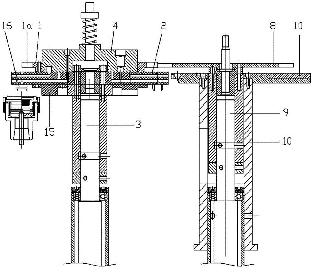
[0024] Example: see Figures 3 to 7 As shown, the feeding and unloading device of the anti-jump cap bottle cap molding machine includes the lower cover plate 1, the feeding plate 2 and the cap feeding plate 8 of the bottle cap molding machine, and the lower cover plate 1 and the feeding plate 2 are coaxial. It is fixed on the rotating shaft 3 of the feeding tray, and the scraping nozzle 16 is fixed on the feeding tray 2. A first suction channel 21 is formed on the feeding tray 2, and an air outlet 23 is formed on the first suction channel 21 to allow ventilation. The block 4 is buckled on the feeding tray 2, and the first suction nozzle 5 is formed on the ventilation block 4, and the first suction nozzle 5 is connected with the first suction channel 21, and the ventilation block 4 is inserted and sleeved on the rotating shaft 3 of the feeding tray. On the top, the spring 6 is inserted and sleeved on the feeding disc shaft 3, the nut 7 is screwed on the feeding disc shaft 3, th...


PUM


Abstract

The invention discloses a feeding and discharging device of a bottle cover moulding press for preventing bottom covers from jumping. A suction channel for preventing bottom covers from jumping is moulded on a feeding disc, a suction hole for preventing bottom covers from jumping is formed in the suction channel and positioned below a center of circle of a bottle cover discharging semicircular notch, a second suction nozzle is moulded on a ventilating block and communicated and connected with the suction channel for preventing bottom covers from jumping; a blowing pipe bracket is fixedly arranged on a cover feeding disc rotating shaft bracket, an S-shaped blowing pipe is fixedly arranged on the blowing pipe bracket, a small blowing hole is moulded in the lower part of the blowing pipe and faces towards suction holes for preventing bottom covers from jumping; a blowing nozzle is moulded on the ventilating block, and communicated and connected with the suction channel; a heat-radiating sheet is fixedly arranged at the lower part of the feeding disc. According to the feeding and discharging device, demoulded bottle covers can be kept on correct positions without being damaged; sizing materials are cooled by adopting a heat-radiating disc, thus the production cost is saved; the sizing materials all accurately fall in a lower mould of the bottle cover moulding press, and a scraping nozzle is assembled, disassembled and maintained very conveniently at the same time.

Description

Technical field: [0001] The invention relates to the technical field of bottle cap molding machines, and more specifically relates to a device for preventing bottle caps from bouncing off on a feeding and unloading device of a bottle cap molding machine. Background technique: [0002] Such as figure 1 , 2 As shown, the existing plastic bottle cap compression molding machine includes an upper mold A1 and a lower mold A2, and the upper mold A1 stretches into the lower mold A2 to extrude the hot-melt glue into a bottle cap, and its feeding and unloading device includes The lower cover tray A3 and the feeding tray A4, the lower part of the feeding tray A4 is provided with a scraper nozzle A5, the scraper nozzle A5 scrapes the hot melt glue on the upper nozzle A6 into the lower mold A2, and the pressed bottle cap passes through The blanking baffle is taken off from the upper mold A1 to the feeding tray A4. Its shortcomings are: 1. When the bottle cap is removed from the upper ...

Claims


Application Information

Patent Timeline
Patent Type & Authority Patents(China)
IPC IPC(8): B29C43/50B29C43/52B29C43/34B29L31/56
CPCB29C43/34B29C43/50B29C43/52B29L2031/56
Inventor 季锋金土良季家栋冯凯杰金文广
Owner SHAOXING HUANGGUAN MACHINERY
Learn More