Device for controlling electric motor and method for controlling electric motor
一种控制装置、电动机的技术,应用在电动机控制、电动发电机控制、交流电动机控制等方向,能够解决转矩级差、司机不协调等问题
- Summary
- Abstract
- Description
- Claims
- Application Information
AI Technical Summary
Problems solved by technology
Method used
Image

Examples
no. 1 approach
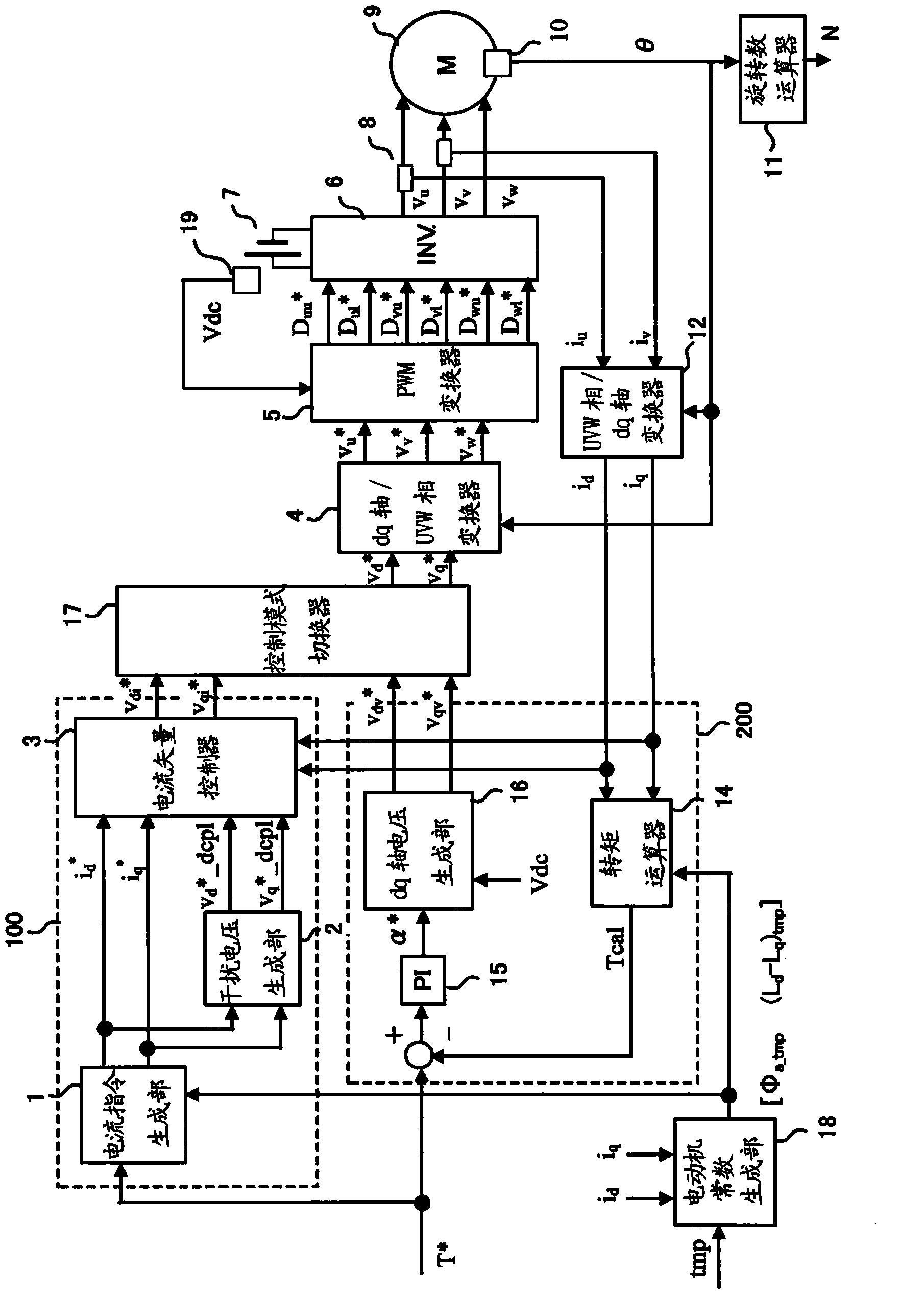
[0015] figure 1 is a control block diagram of motor control in the first embodiment. This control is executed according to a flowchart described later.
[0016] This control is executed by switching between the current control mode and the voltage phase control mode according to the operating state of the motor. The current control mode is a control mode based on a current command value based on a motor constant corresponding to the magnet temperature of the motor 9 and a torque command value. The voltage phase control mode is a control mode in which torque feedback operation is performed on the voltage phase based on the deviation between the torque estimated value and the torque command value based on the torque calculation formula. In addition, the mode is switched to the voltage phase control mode in a high-rotation region where flux-weakening control is performed.
[0017] figure 1 The current control unit 100 includes a current command generation unit 1, a disturba...
no. 2 approach
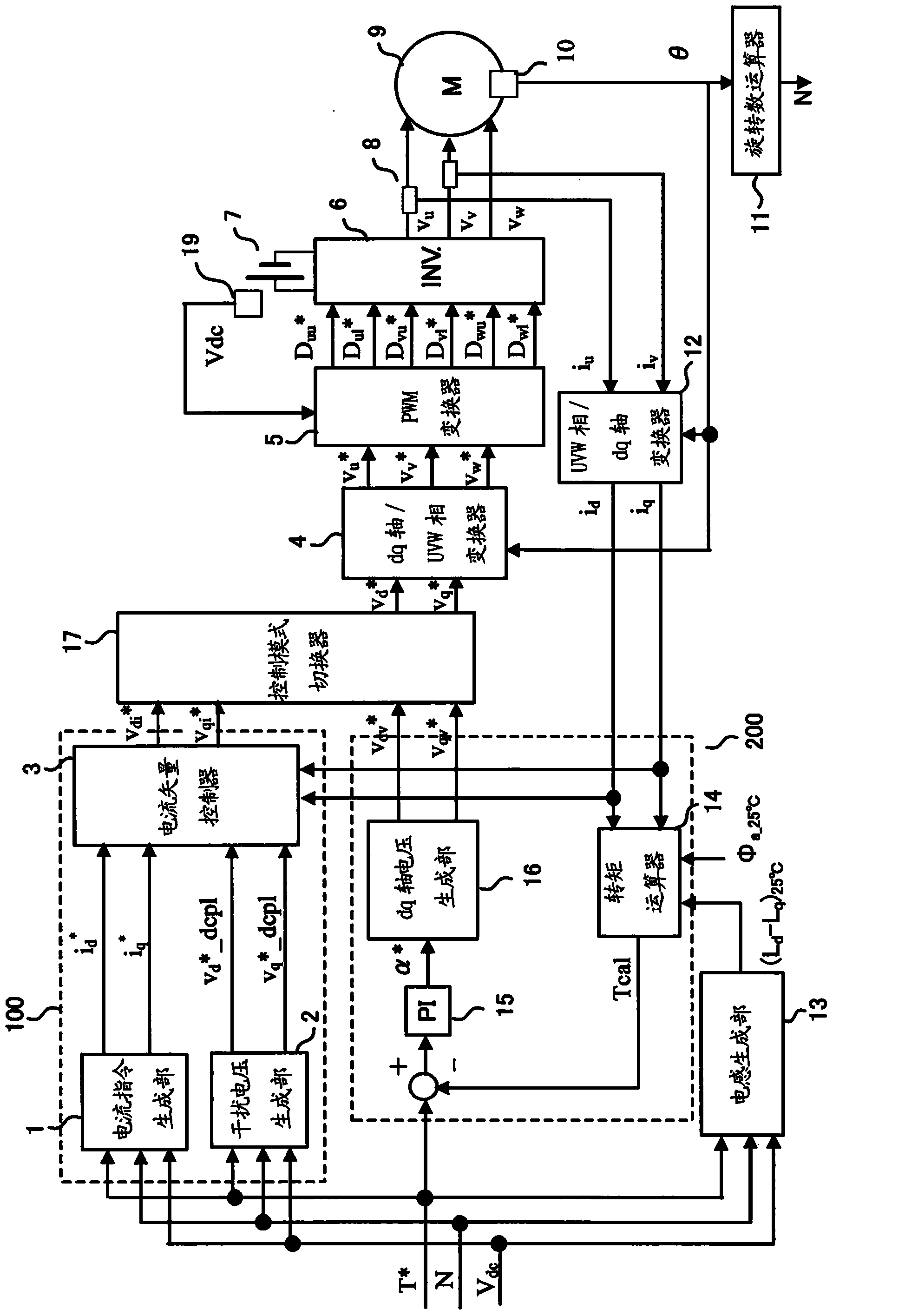
[0053] figure 2 It is a control block diagram of motor control in the second embodiment. This control is executed according to a flowchart described later.
[0054] In this embodiment, the magnet temperature tmp is set to a fixed value (25° C.), and the inductance generating unit 13 is provided instead of the motor constant generating unit 18 . In addition, in this way, the calculation contents of the current control unit 100 and the voltage phase control unit 200 are different from those of the first embodiment. Hereinafter, differences from the first embodiment will be described. In addition, 25° C. is a temperature set based on the performance guarantee temperature or the operating environment temperature when the magnet temperature tmp is a fixed value, but is not limited thereto.
[0055] The current control unit 100 will be described.
[0056] The torque command value T is input to the current command generator 1 * , rotation speed N, and battery voltage V dc , re...
no. 3 approach
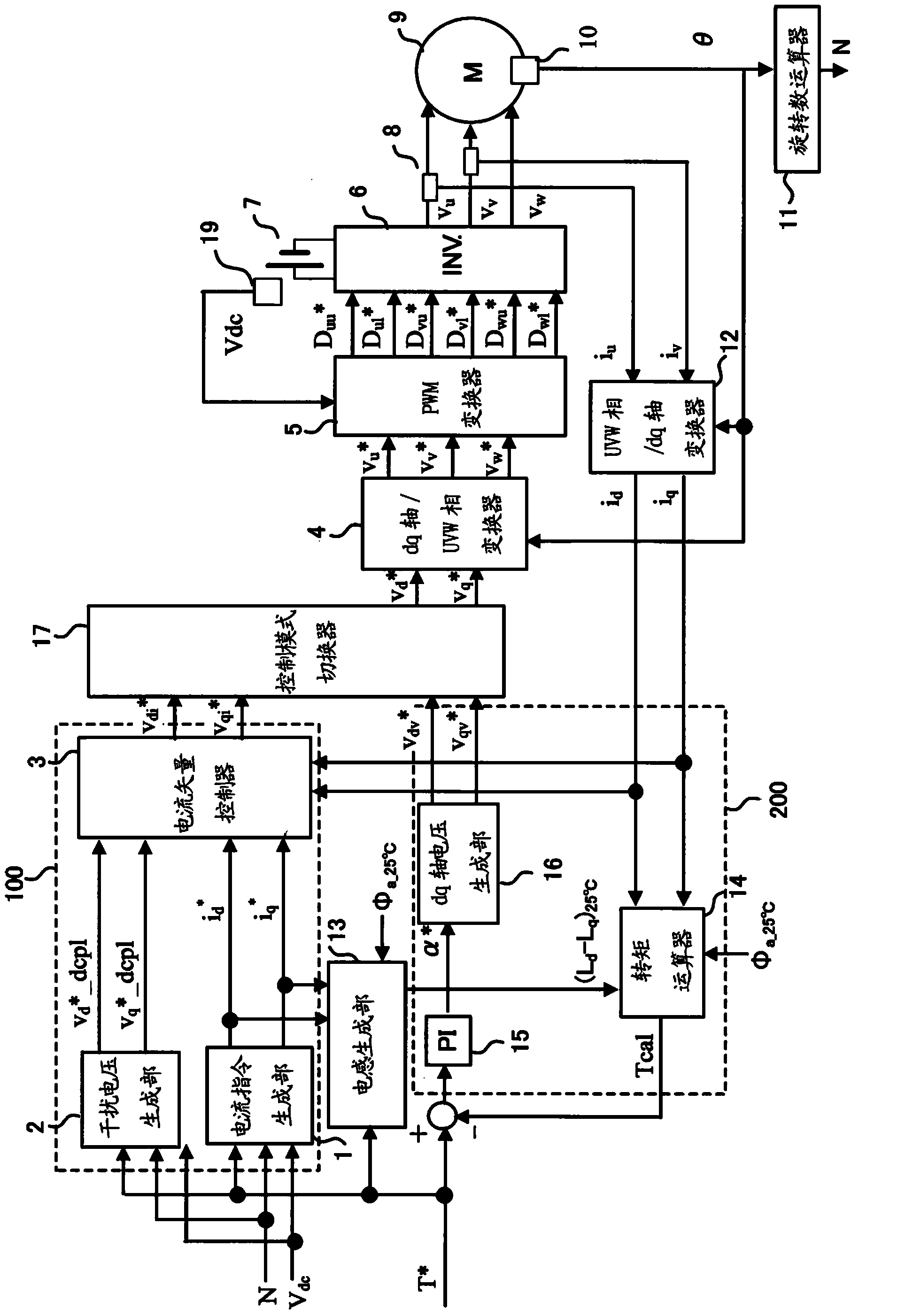
[0066] image 3 is a control block diagram of motor control in the third embodiment. This control is executed according to a flowchart described later.
[0067] Hereinafter, differences from the second embodiment will be described.
[0068] The torque command value T is input to the current command generator 1 and the disturbance voltage generator 2 * , rotation speed N, and battery voltage V dc , refer to the table generated by previous experiments or calculations, generate and output the dq-axis current command value i in the case of tmp=25°C d *, i q *And dq axis interference voltage value v d * _dcpl , v q * _dcpl . However, as a premise for creating the table, the modulation factor M in the saturation region of the motor applied voltage, that is, the flux weakening region * and in the dq-axis voltage generator 16 according to the voltage phase command value α * Calculate the dq-axis voltage command value v for the voltage phase control mode dv * , v qv * ...
PUM
 Abstract
Description
Claims
Application Information
 - Generate Ideas
- Intellectual Property
- Life Sciences
- Materials
- Tech Scout
- Unparalleled Data Quality
- Higher Quality Content
- 60% Fewer Hallucinations
Browse by: Latest US Patents, China's latest patents, Technical Efficacy Thesaurus, Application Domain, Technology Topic, Popular Technical Reports.
© 2025 PatSnap. All rights reserved.Legal|Privacy policy|Modern Slavery Act Transparency Statement|Sitemap|About US| Contact US: help@patsnap.com