
Device and method for realizing mass transmission of virtual cloud graphic workstation

A graphic workstation and transmission device technology, applied in the transmission system, data exchange through path configuration, electrical components, etc., can solve the problems of increased power consumption, difficult construction, and high cost of quartz optical fibers in data centers and cooling systems, and achieve easy Maintenance and management, realizing massive data transmission, and simplifying the effect of a lot of work

Active Publication Date: 2015-02-04
武汉理工数字传播工程有限公司
View PDF4 Cites 2 Cited by
  • Summary
  • Abstract
  • Description
  • Claims
  • Application Information

AI Technical Summary

Problems solved by technology

[0003] (1) Using plastic as the main carrier of optical fiber, the transmission loss is relatively large, and long-distance transmission cannot be realized;
[0004] (2) The cost of the existing silica optical fiber for sunlight transmission is very high, and during the transmission process of the silica optical fiber, one optical fiber can only correspond to one light-emitting point. If the area to be illuminated is large, a large number of optical fibers is required. In this way, the diameter of the optical fiber after being cabled is too thick, which also causes great difficulties in construction.
[0009] (2) The increasing number of servers leads to an increase in power consumption of research institutions or company data centers and cooling systems, which has a negative impact on the environment
[0010] (3) The terminal uses a heterogeneous hardware environment, causing potential safety hazards that cannot be ignored for software compatibility and upgrade maintenance of graphics workstations

Method used


Image

  • Device and method for realizing mass transmission of virtual cloud graphic workstation
  • Device and method for realizing mass transmission of virtual cloud graphic workstation
  • Device and method for realizing mass transmission of virtual cloud graphic workstation

Examples


Embodiment 1

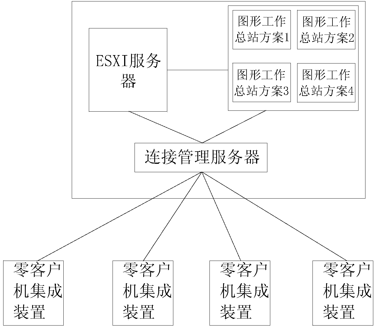
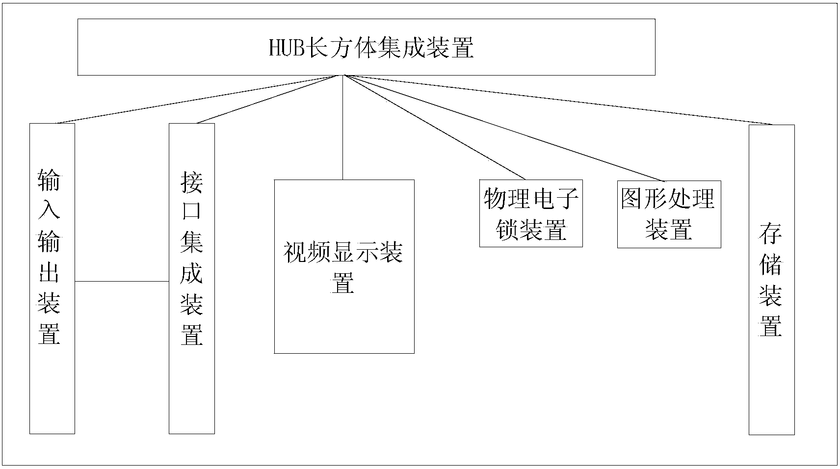
[0032] Example 1, such as Figure 1-2 As shown, a device for realizing mass transmission of a virtual cloud graphics workstation described in an embodiment of the present invention includes: a virtual cloud graphics workstation and a zero client integration device; the virtual cloud graphics workstation includes an ESXI server inside, and the ESXI server and The graphics workstation is connected, and the ESXI server and the graphics workstation are respectively connected to the connection management server; at present, there is a standard that supports HDMI2USB3.0, that is, a high-definition data interface. This can be used as an advanced configuration, and the data transmission rate is further improved. The virtual cloud graphics workstation includes a workstation, an ESXI server and a connection management server, the graphics workstation and the ESXI server are connected to the connection management server, and the connection management server is connected externally. The ...


PUM

PropertyMeasurementUnit
Thicknessaaaaaaaaaa

Abstract

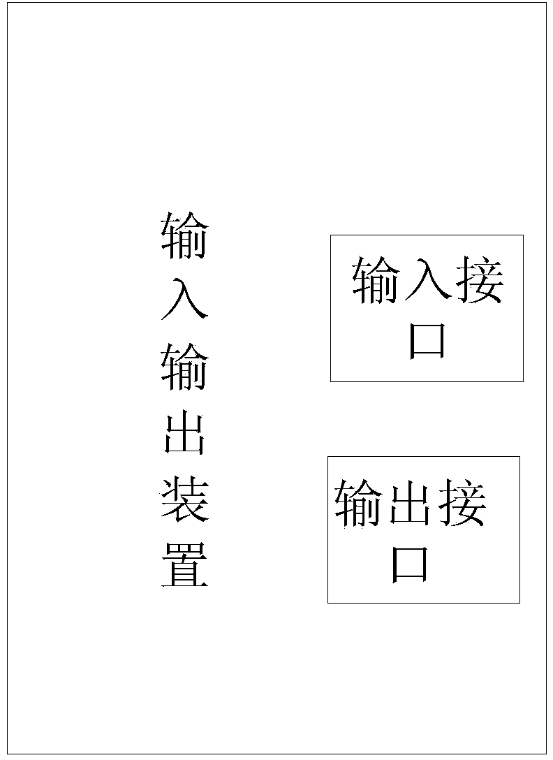
The invention provides a device for realizing mass transmission of a virtual cloud graphic workstation, the virtual cloud graphic workstation and a zero client integrated device. The virtual cloud graphic workstation internally comprises an ESXI server which is connected with the graphic workstation; the ESXI server and the graphic workstation are connected with the management server, respectively; the zero client integrated device comprises an HUB cuboid integrated device which is connected with an input / output device, an interface integrated device, a video display device, a physical electronic lock device, a graphic processing device and a storing device, respectively. The device for realizing mass transmission of the virtual cloud graphic workstation has the beneficial effects that the mass work of implementation of the large-scale cloud graphic workstation is simplified, and the successfully set-up cloud graphic workstation integrated system is easy to maintain and manage, the purpose of mass data transmission of the virtual cloud graphic workstation is achieved, and meanwhile, an active optical fiber and zero client integrated virtual cloud graphic workstation system convenient for customers to access quickly is also set up.

Description

technical field [0001] The invention relates to a mass transmission device and transmission method for a virtual cloud graphics workstation. Background technique [0002] With the development of optical fiber technology, the application of active optical fiber technology has replaced the dominant position of traditional passive optical fiber. Among them, the typical lighting device uses sunlight lighting technology, tracks the sun's trajectory, and gathers sunlight to the maximum. At present, a large number of related technologies have been disclosed and used in this respect. The defects and deficiencies in the actual application of the prior art of optical fiber are as follows: [0003] (1) Using plastic as the main carrier of optical fiber, the transmission loss is relatively large, and long-distance transmission cannot be realized; [0004] (2) The cost of the existing silica optical fiber for sunlight transmission is very high, and during the transmission process of th...

Claims


Application Information

Patent Timeline
IPC IPC(8): H04L29/08H04L12/28
CPCH04L67/08H04L67/10
Inventor 白立华刘永坚黄卫军周恒杨朝阳
Owner 武汉理工数字传播工程有限公司
Learn More