
An Improved Blast Furnace

An improved technology for blast furnaces, applied in furnaces, vertical furnaces, furnace components, etc., can solve the problems of long continuous working hours of blast furnaces, small daily processing raw materials, high smoke and dust rate of exhaust gas, etc., and achieve long continuous working hours and maintenance times The effect of less, high amount of processing raw materials

Active Publication Date: 2015-11-11
永兴县荣鹏金属有限公司
View PDF8 Cites 1 Cited by
  • Summary
  • Abstract
  • Description
  • Claims
  • Application Information

AI Technical Summary

Problems solved by technology

[0003] In order to overcome the shortcomings of the existing smelting enterprises using blast furnaces for production, the amount of raw materials processed per unit bottom area of ​​the blast furnace is small, the smoke and dust rate in the waste gas is high, and the furnace is easy to "dead furnace". The invention provides an improved blast furnace. An improved blast furnace, which can make the daily raw material processing capacity per unit bottom area of ​​the blast furnace reach 35-40 tons per square meter per day; the smoke and dust rate in the exhaust gas can be reduced to 5%-6%; at the same time, the blast furnace can work continuously for a long time. During the year, the number of production shutdowns due to "dead furnaces" was reduced from 4-6 times to 1-3 times

Method used


Image

  • An Improved Blast Furnace
  • An Improved Blast Furnace
  • An Improved Blast Furnace

Examples


Embodiment Construction

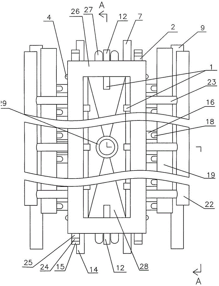
[0032] exist figure 1 , Figure 2, image 3 In the shown embodiment, the base 11 of the blast furnace is built by heat-resistant bricks, and there is a row of coarse lead holes 30 in the base 11, and a row of coarse lead grooves 10 is installed at the outlet of the row of coarse lead holes 30.

[0033] The left and right side walls of the blast furnace are respectively composed of a set of upper water jackets 3 and a set of lower water jackets 6. The adjacent upper water jackets 3 and lower water jackets 6 are connected by water jacket connecting pipes 5. Each upper water jacket 3 A water outlet branch pipe 23 communicates with the water outlet main pipe 22 of the water jacket, and each lower water jacket 6 communicates with the water jacket water inlet main pipe 9 through a water jacket water inlet branch pipe 8; each lower water jacket 6 has two inlet inclined pipes 16 Pass through, the upper end of each air intake inclined pipe 16 has observation hole, the observation hole ...


PUM


Abstract

The invention relates to an improved novel blast furnace. A base is built by heat resistant bricks, coarse lead discharging holes are formed in the base, the left side wall and the right side wall of the base are respectively formed by one group of upper water sleeves and one group of lower water sleeves, the adjacent upper water sleeves and lower water sleeves are communicated by water sleeve communicating pipes, two air inlet inclined pipes penetrate through each lower water sleeve, and each air inlet inclined pipe is communicated with an air inlet main pipe through one air inlet branch pipe. The front and back walls are respectively formed by two upper water sleeve doors, two middle water sleeve doors and a lower water sleeve door, an upper water sleeve door water outlet pipe is arranged on each upper water sleeve door, a middle water sleeve door water inlet pipe is arranged on each middle water sleeve door, the adjacent upper water sleeve doors and middle water sleeve doors are communicated through water sleeve doors, and each lower water sleeve door is provided with a lower water sleeve door water outlet pipe, a slag discharge pipe and a lower water sleeve door water inlet pipe. The upper part of the novel blast furnace is provided with a water sleeve frame, a water sleeve frame water outlet pipe and a water sleeve frame water inlet pipe are arranged on the water sleeve frame, a gas collecting cover is connected with the water sleeve frame through a connecting frame, and the upper end of the gas collecting cover is provided with an exhaust pipe.

Description

technical field [0001] The present invention relates to an improved blast furnace. Background technique [0002] At present, the known blast furnaces used by smelting enterprises do not use inclined pipes at a certain angle to the horizontal line to supply air, resulting in poor air penetration in the blast furnace and narrow oxygen coverage, resulting in a small amount of raw materials processed per unit bottom area of ​​the blast furnace (per day per day) 25-30 tons of raw materials per square meter), and the dust rate in the waste gas is high (12%-18%), the recovery rate of useful metals is low, and the production efficiency of the blast furnace is low. The second is that there is no discharge of liquid slag at both ends, and after a period of operation of the blast furnace, it is easy to "dead furnace" and needs to be shut down for maintenance, resulting in an increase in the production cost of the blast furnace. Contents of the invention [0003] In order to overcome...

Claims


Application Information

Patent Timeline
Patent Type & Authority Patents(China)
IPC IPC(8): F27B1/00F27B1/24F27B1/16F27D1/18F27B1/21
Inventor 李荣鹏侯千驹雷兴国胡波曹咏梅
Owner 永兴县荣鹏金属有限公司
Learn More