
A device and method for measuring gas pressure using ultrasonic waves

A gas pressure and ultrasonic technology, applied in measurement, earthwork drilling, wellbore/well components, etc., can solve problems such as inaccurate pressure measurement, long time-consuming pressure measurement, poor sealing quality, etc., to achieve accurate measurement and save work Time and precision are high

Active Publication Date: 2017-06-06
ANHUI UNIV OF SCI & TECH
View PDF7 Cites 0 Cited by
  • Summary
  • Abstract
  • Description
  • Claims
  • Application Information

AI Technical Summary

Problems solved by technology

However, the existing drilling methods for gas pressure measurement mainly involve pre-drilling, placing pressure sensors, plugging and drainage drilling, and measuring pressure. The quality of the hole sealing is poor, and the workers take care of the instrument for a long time. Long time, low pressure measurement efficiency, and inaccurate pressure measurement

Method used


Image

  • A device and method for measuring gas pressure using ultrasonic waves
  • A device and method for measuring gas pressure using ultrasonic waves
  • A device and method for measuring gas pressure using ultrasonic waves

Examples


Embodiment 1

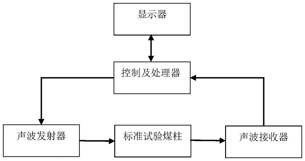
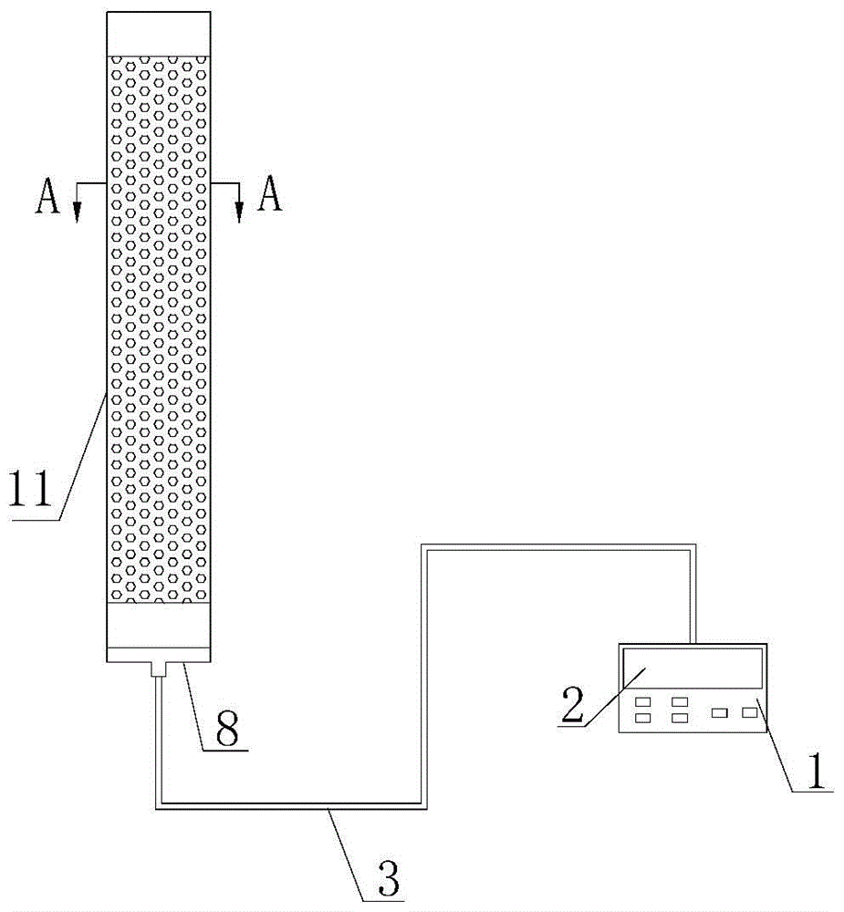
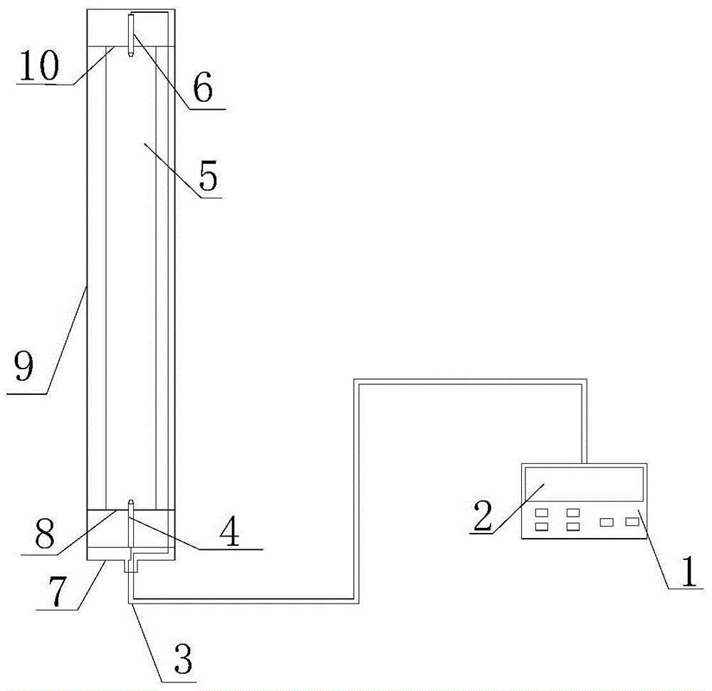
[0028] Such as figure 1 , figure 2 , image 3 with Figure 4 As shown, a device for measuring gas pressure using ultrasonic waves includes a sonic instrument, a wire 3, a controller and a processor 1, and a display 2. The sonic instrument includes a casing 9, a closing cover 7, a lower coal plate 8, and an upper coal plate 10. Acoustic wave transmitter 4, standard test coal pillar 5 and acoustic wave receiver 6, one end of shell 9 with a length of 500 mm and a diameter of 50 mm is closed, and the other end is open. Made of iron, the outer surface of the shell 9 is covered with mesh holes 11, and the inner surface of the shell 9 is sprayed with a sound-absorbing coating; the standard test coal pillar 5 with a length of 400mm and a diameter of 40mm is placed in the middle of the shell 9, and the standard test coal pillar 5 is complete The complete coal pillar refers to a coal pillar without large cracks or broken coal pillars. One end of the standard test coal pillar 5 is cl...

Embodiment 2

[0036] Such as figure 1 , figure 2 , image 3 with Figure 4 As shown, a device for measuring gas pressure using ultrasonic waves includes a sonic instrument, a wire 3, a controller and a processor 1, and a display 2. The sonic instrument includes a casing 9, a closing cover 7, a lower coal plate 8, and an upper coal plate 10. Acoustic wave transmitter 4, standard test coal pillar 5 and acoustic wave receiver 6, one end of shell 9 with a length of 900 mm and a diameter of 70 mm is closed, and the other end is open. Made of iron, the outer surface of the shell 9 is covered with mesh holes 11, and the inner surface of the shell 9 is sprayed with a sound-absorbing coating; the standard test coal pillar 5 with a length of 800mm and a diameter of 66mm is placed in the middle of the shell 9, and the standard test coal pillar 5 is complete The complete coal pillar refers to a coal pillar without large cracks or broken coal pillars. One end of the standard test coal pillar 5 is cl...


PUM


Abstract

The invention provides a device for measuring gas pressure by using ultrasonic wave. The device comprises a sonic apparatus, a wire, a controlling and processing device and a display, wherein the sonic apparatus comprises a shell, a closing cover, an upper coal clamping plate, a lower coal clamping plate, a sonic emitter, a standard test coal pillar and a sonic receiver; one end of the shell is closed, and the other end of the shell is open; the opening is sealed by using the sealing cover; the standard test coal pillar is placed in the middle of the shell; one end of the standard test coal pillar is clamped by using the lower coal clamping plate, and the other end of the standard test coal pillar is clamped by using the upper coal clamping plate; the lower coal clamping plate is provided with the sonic emitter; one end of the sonic emitter is in contact with the standard test coal pillar, and the other end of the sonic emitter is connected with the controlling and processing device through the wire; the upper coal clamping plate is provided with the sonic receiver; one end of the sonic receiver is in contact with the standard test coal pillar, and the other end of the sonic receiver is connected with the controlling and processing device through the wire. The device provided by the invention has the advantages of accuracy in measurement, convenience in operation, time saving effect, labor saving effect and the like. The invention also provides a method for measuring the gas pressure by using the device.

Description

technical field [0001] The invention relates to a device for measuring coal seam gas pressure, in particular to a device and method for measuring gas pressure by ultrasonic waves. Background technique [0002] Gas gushing and coal and gas outburst accidents often occur in the mining of high-gas mines and outburst mines, which seriously affect and restrict the safe mining of coal and the healthy development of the coal industry. Coal seam gas pressure is one of the important indicators to evaluate the risk of coal seam outburst. Before coal seam mining, the gas pressure of coal seam must be detected in advance, and then corresponding gas drainage measures should be taken. However, the existing drilling methods for gas pressure measurement are mainly pre-drilling, placing pressure sensors, plugging and drainage drilling, and measuring pressure. The quality of the hole sealing is poor, and the workers take care of the instrument for a long time. Long time, low pressure measure...

Claims


Application Information

Patent Timeline
Patent Type & Authority Patents(China)
IPC IPC(8): E21B47/06
CPCE21B47/06
Inventor 穆朝民石必明伍清齐娟张文清胡祖祥高光发程建圣
Owner ANHUI UNIV OF SCI & TECH
Learn More