a slag furnace

A slag furnace and slag technology, applied in the field of slag high-temperature melt, can solve the problem that heat cannot be recycled, and achieve the effect of simple structure, high mixing efficiency and uniform melting

Inactive Publication Date: 2016-03-30
宝钢矿棉科技(宁波)有限公司
View PDF2 Cites 0 Cited by
  • Summary
  • Abstract
  • Description
  • Claims
  • Application Information

AI Technical Summary

Problems solved by technology

Since blast furnace slag is widely used, the principle of energy recovery of slag is not only to recover residual heat resources, but also to facilitate the reuse of slag. While making full use of the sensible heat of waste slag, produce mineral wool, slag glass ceramics, etc. Building material products with high added value; but at present, most blast furnace slags at home and abroad are mainly water-quenched, and the heat cannot be recycled

Method used


Image

  • a slag furnace
  • a slag furnace
  • a slag furnace

Examples


Embodiment Construction

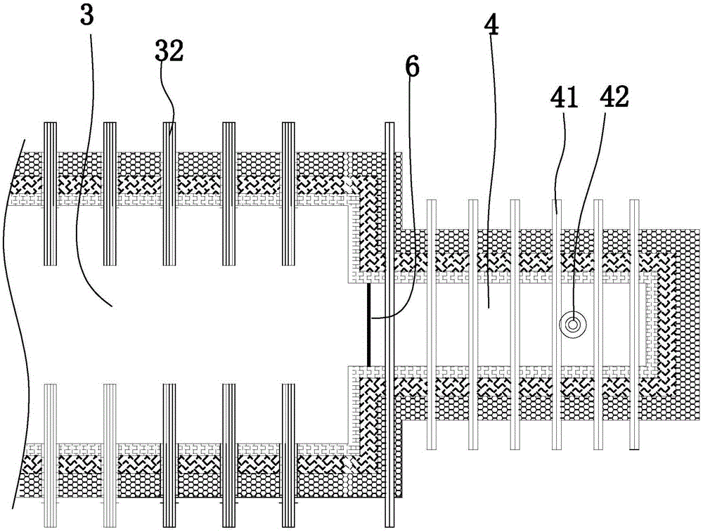
[0038] Below in conjunction with accompanying drawing and specific embodiment the present invention is described in further detail:

[0039] like figure 1 As shown, a slag furnace includes a feeding pool 1, a homogenizing pool 2, a melting pool 3 and a forehearth 4 in sequence. The homogenization pool is located between the feeding pool and the melting pool. The feeding pool and the melting pool are connected 7 through the first liquid flow channel, specifically, the first liquid flow channel communicates with the feeding pool and the homogenization pool. The bottom of the feeding tank is provided with a liquid outlet of the feeding tank, and the bottom of one side of the homogenizing tank is provided with a liquid inlet 71 of the homogenizing tank, and the first liquid channel connects the liquid outlet of the feeding tank and the liquid inlet of the homogenizing tank. The bottom of the homogenizing tank and the bottom of the melting tank are communicated 8 through a second...


PUM


Abstract

The invention discloses a slag furnace and aims to provide the slag furnace which not only can fully utilize residual heat resources in blast furnace thermal-state slag and is energy-saving and environmental-protective but also can enable a melt in a slag furnace to be melted uniformly, a vitrification degree to be high and a fiber-forming ratio and quality of mineral wool to be improved. The slag furnace successively includes a feeding tank, a melting tank and a material path. A slag flow inlet and a main modulating material feeding port are arranged on an upper part of the feeding tank. The feeding tank is connected to the melting tank through a first liquid flowing path. One end of the material path is communicated with the melting tank and the other end of the material path is closed. In addition, a material outlet port is arranged at the bottom of the material path. A first flow-controlling gate board device is disposed at the first liquid flowing path and is used for controlling the flow rate of the first liquid flowing path. A material path flow-controlling gate board device is disposed at the material path and is used for controlling the flow rate of the material path. The material path flow-controlling gate board device is arranged between the melting tank and the material outlet port and is closed to the melting tank.

Description

technical field [0001] The invention relates to the technical field of slag high-temperature melt, in particular to a slag furnace for processing blast furnace hot slag. Background technique [0002] With the rapid development of the global economy, the problem of energy shortage is becoming more and more serious, and the technology of energy saving and emission reduction has become a research hotspot all over the world. At present, my country's energy situation is severe, and the product energy consumption index is too high. The energy consumption per unit of the main energy-consuming products is 25-90% higher than that of developed countries (the weighted average is about 40% higher); secondly, the energy consumption of the output value is high. Energy consumption is one of the highest in the world. For example, for every kilogram of oil equivalent of energy, Japanese companies can create an average output value of 10.2 US dollars, while China can only create 0.7 US dollars...

Claims


Application Information

Patent Timeline
Patent Type & Authority Patents(China)
IPC IPC(8): C21B3/06
CPCY02W30/50
Inventor 陈铁军王品益朱春江李胜春沈健高晓骏
Owner 宝钢矿棉科技(宁波)有限公司
Why Eureka
Try Eureka