A new type of perforated frame supporting jacking structure

A jacking and perforating technology, applied in the direction of lifting devices, can solve the problems of inconvenient construction, hidden dangers of construction safety, low efficiency, etc., and achieve the effects of easier operation, safe drilling and stable structure

Active Publication Date: 2017-01-04
ZHEJIANG QIAOXING CONSTR GRP
View PDF9 Cites 0 Cited by
  • Summary
  • Abstract
  • Description
  • Claims
  • Application Information

AI Technical Summary

Problems solved by technology

At present, many projects require drilling holes to install suspenders (screws) for indoor ceiling operations such as ceilings, bridge frames, and lamps. When drilling holes, two people are required to operate. One of them is a ladder, and the other is an escalator. The construction is inconvenient for the person who works with the ladder. , low efficiency, and potential safety hazards

Method used


Image

  • A new type of perforated frame supporting jacking structure
  • A new type of perforated frame supporting jacking structure
  • A new type of perforated frame supporting jacking structure

Examples


Embodiment 1

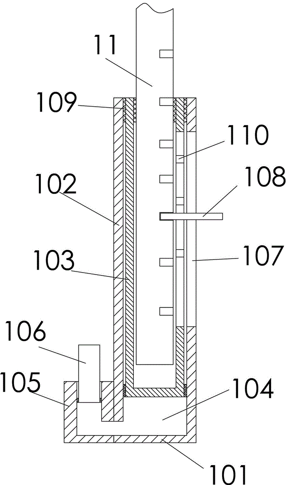
[0034] A novel perforated frame support jacking structure, comprising a support base and a support rod 11 inserted on the support base, the support base includes a base plate 101 and an outer casing 102 vertically arranged on the base plate; the support rod Inserted in the outer casing along the axial direction of the outer casing, the inner bottom of the outer casing is provided with a hydraulic oil chamber 104 for lifting the support rod, and the outer casing is also provided with a hydraulic cylinder 105 communicating with the hydraulic oil chamber. The cylinder is inserted with a piston rod 106 that can press the oil in the hydraulic cylinder into the hydraulic oil cavity for lifting the support rod. Linear bearings 109 are fixed at the upper ends of the lumens of the inner sleeve and the outer sleeve.

[0035] The support base also includes an inner sleeve 103 that is inserted in the outer sleeve along the axial direction of the outer sleeve and can slide up and down alon...

Embodiment 2

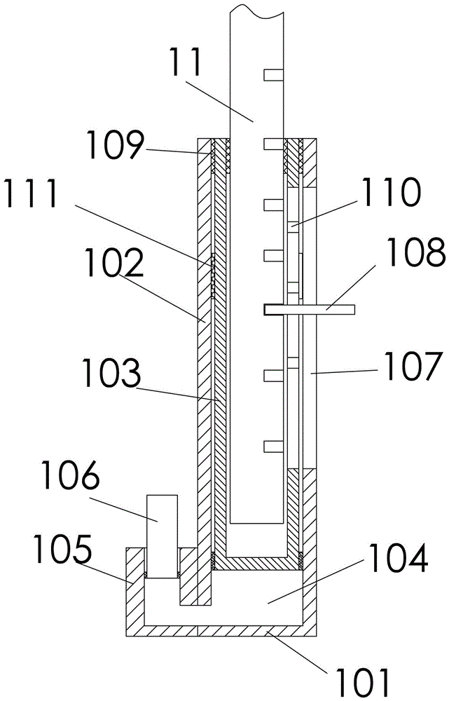
[0039] The difference from the above embodiments is that the base plate is provided with a stud tube 112 with external threads, and the inner wall of the lower end of the outer sleeve is provided with internal threads that are screwed and adapted to the stud tube, and the wall of the stud tube is A through hole for connecting the hydraulic oil chamber and the hydraulic cylinder is opened on the top.

Embodiment 3

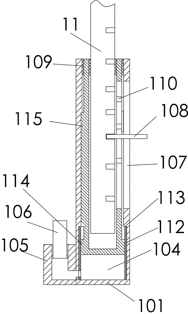
[0041]The difference from the above-mentioned embodiment is that the lower part of the inner wall of the outer sleeve is recessed outward to form a limit step 113, and the outer wall of the inner sleeve is convexly formed below the limit step and is used to limit the inner sleeve up and down with the limit step. The stop step 114 of the sliding travel range. The inner wall of the outer sleeve and the outer wall of the inner sleeve are respectively provided with adapted guide ribs (115) and guide grooves along the axial direction of the outer sleeve. Therefore, it is used to prevent the inner sleeve from rotating in the outer sleeve in the circumferential direction, and ensure that the handle does not drive the inner sleeve when the support rod is rotated to prevent the positioning transverse groove from being covered by the outer sleeve. It can also play a guiding role and make the entire structure Movement is more stable.


PUM


Abstract

The invention relates to the field of architectural decoration, in particular to a novel punching frame supporting jacking structure. It includes a support base and a support rod inserted on the support base. The support base includes a base plate and an outer sleeve vertically arranged on the base plate; the support rod is inserted in the outer sleeve along the axial direction of the outer sleeve, and the outer sleeve A hydraulic oil chamber for lifting the support rod is provided at the bottom of the pipe, and a hydraulic cylinder communicating with the hydraulic oil chamber is provided outside the outer casing, and a hydraulic cylinder is inserted on the hydraulic cylinder to press the oil in the hydraulic cylinder into the hydraulic oil chamber. The cavity is used to lift the piston rod of the support rod. In this application, the handle can be used to lift the support rod upward along the through groove to lift the puncher installed on the top of the support rod, and the piston rod can be pressed down to press the hydraulic oil in the piston rod into the hydraulic oil chamber. Thereby jacking up the support bar, the operation is diverse and convenient, the support bar rises steadily, and the drilling is safer.

Description

technical field [0001] The invention relates to the field of architectural decoration, in particular to a novel punching frame supporting jacking structure. Background technique [0002] The structural layer or decoration house on the upper part of the existing indoor space is mostly equipped with a ceiling (suspended ceiling) to cover the structural layer of the roof to meet the requirements of indoor use. At present, many projects require drilling holes to install suspenders (screws) for indoor ceiling operations such as ceilings, bridge frames, and lamps. When drilling holes, two people are required to operate. One of them is a ladder, and the other is an escalator. The construction is inconvenient for the person who works with the ladder. , the efficiency is low, and there are potential safety hazards in construction. In order to solve this problem, the simple punching frame with the Chinese patent No. 201120157482.3 adopts a bracket with a supporting wooden square and ...

Claims


Application Information

Patent Timeline
Patent Type & Authority Patents(China)
IPC IPC(8): B66F13/00
Inventor 宋霞萍洪晨李翔陈伟张思懿蒋琪
Owner ZHEJIANG QIAOXING CONSTR GRP
Why Eureka
Try Eureka