
Optical imaging small satellite attitude control system and working mode on-orbit switching method

A technology of satellite attitude control and optical imaging, applied in the field of satellite attitude control, to achieve a wide range of effects

Active Publication Date: 2016-08-17
HARBIN INST OF TECH
View PDF3 Cites 0 Cited by
  • Summary
  • Abstract
  • Description
  • Claims
  • Application Information

AI Technical Summary

Problems solved by technology

[0004] The purpose of the present invention is to solve the problem that existing optical imaging satellites cannot simply and effectively realize on-orbit switching, and provide a small optical imaging satellite attitude control system and a working mode on-orbit switching method

Method used


Image

  • Optical imaging small satellite attitude control system and working mode on-orbit switching method
  • Optical imaging small satellite attitude control system and working mode on-orbit switching method

Examples


specific Embodiment approach 1

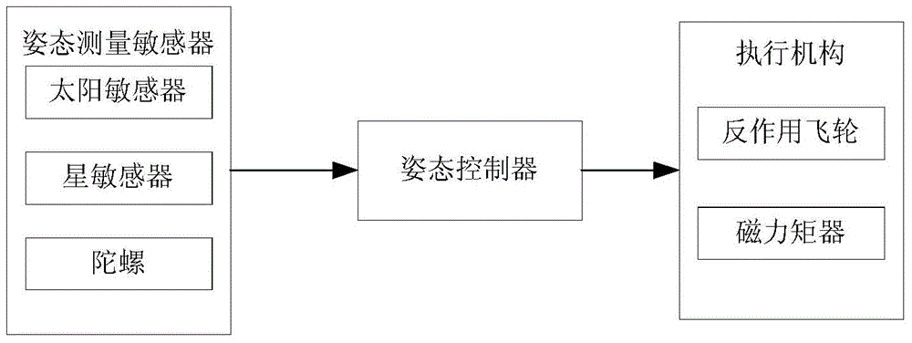
[0017] Specific implementation mode one: the following combination figure 1 Describe this embodiment, the optical imaging small satellite attitude control system described in this embodiment includes an attitude measurement sensor, an actuator, and an attitude controller, and the attitude measurement sensor measures satellite attitude information and sends the attitude information to the attitude controller ; The attitude controller receives the attitude information sent by the attitude measurement sensor, generates a control instruction through calculation, and sends it to the actuator; the actuator receives the control instruction sent by the attitude controller, and generates a corresponding torque to act on the satellite.

specific Embodiment approach 2

[0018] Specific implementation mode two: the following combination figure 1 Illustrate this embodiment, this embodiment will be further described to embodiment one, and described attitude measurement sensor comprises sun sensor, star sensor and gyroscope; Sun sensor is used for measuring satellite attitude angle, and star sensor is used for measuring satellite attitude angle, The gyroscope is used to measure the satellite attitude angular velocity; the actuator includes a reaction flywheel and a magnetic torque device; the reaction flywheel is used for maneuver control and three-axis stability control of the satellite; the magnetic torque device is used for damping control of the satellite; the attitude controller adopts attitude information processing The unit is realized.

specific Embodiment approach 3

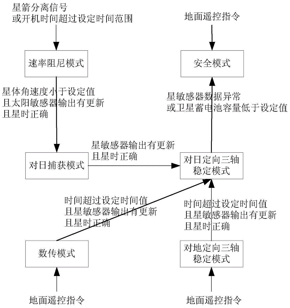
[0019] Specific implementation mode three: the following combination figure 2 This embodiment will be described. The on-orbit switching method of the working mode based on the attitude control system of the optical imaging small satellite described in this embodiment is to set the attitude control system of the optical imaging small satellite into six working modes, which are: rate damping mode, Acquisition mode, sun orientation three-axis stabilization mode, ground orientation three-axis stabilization mode, data transmission mode and security mode;

[0020] The on-orbit switching methods of the six working modes are as follows:

[0021] The switching method of the rate damping mode is as follows: when the satellite receives the satellite-rocket separation signal sent by the separation mechanism, or the attitude information processing unit starts up for more than the set time range, it will switch to the rate damping mode;

[0022] The switching method of the sun acquisition...


PUM


Abstract

The invention discloses an optical imaging minisatellite attitude control system and an in-orbit working mode switching method, belongs to the field of satellite attitude control and aims at solving the problem that existing optical imaging satellites cannot be simply and effectively switched in the orbit. The optical imaging minisatellite attitude control system comprises an attitude measurement sensor, an actuating mechanism and an attitude controller, wherein the attitude measurement sensor comprises a sun sensor, a star sensor and a gyroscope; the actuating mechanism comprises a counteraction flywheel and a magnetorquer. According to an in-orbit working mode switching method of the optical imaging minisatellite attitude control system, the optical imaging minisatellite attitude control system has six working modes, namely a rate damping mode, a sun capture mode, a sun-orientated three-axis stabilization mode, an earth-orientated three-axis stabilization mode, a data transmission mode and a safety mode. The optical imaging minisatellite attitude control system and the in-orbit working mode switching method are suitable for all the optical imaging minisatellites.

Description

technical field [0001] The invention relates to an attitude control system of an optical imaging small satellite and an on-orbit switching method of a working mode, belonging to the field of attitude control of satellites. Background technique [0002] Optical imaging small satellites, as typical earth observation satellites, have the advantages of short development period and flexible launch, and are currently a research hotspot at home and abroad. my country's high-resolution earth observation system (referred to as "high-resolution special project") is one of the 16 major special projects determined in the "National Medium and Long-term Science and Technology Development Plan (2006-2020)", which was approved by the State Council in 2010 Start the implementation. On April 27, 2013, the first star "Gaofen-1" was successfully launched at the Jiuquan Satellite Launch Center with the Long March 2D carrier rocket. [0003] Optical imaging small satellites put forward high requ...

Claims


Application Information

Patent Timeline
Patent Type & Authority Patents(China)
IPC IPC(8): B64G1/36B64G1/24
Inventor 陈雪芹王峰李冬柏陈健李化义叶东张刚耿云海
Owner HARBIN INST OF TECH
Learn More