
A method of using a glove box with a purification system

A purification system and glove box technology, applied in the field of glove boxes, can solve the problems of unscientific reduction gas flow control, unreasonable purification column structure design, unscientific height-diameter ratio design, etc., so as to increase the reduction time, frequency and cost. , the effect of reducing utilization

Active Publication Date: 2017-02-08
长沙天创粉末技术有限公司
View PDF7 Cites 0 Cited by
  • Summary
  • Abstract
  • Description
  • Claims
  • Application Information

AI Technical Summary

Problems solved by technology

At present, some manufacturers in the industry frequently restore and clean products. In addition to the problems of sealing and regeneration of purification materials, there are unreasonable structural design of purification columns, unscientific design of height-to-diameter ratio, and unscientific flow control of reducing gas. Factors such as incomplete restoration and regeneration each time

Method used


Image

  • A method of using a glove box with a purification system
  • A method of using a glove box with a purification system
  • A method of using a glove box with a purification system

Examples


Embodiment 1

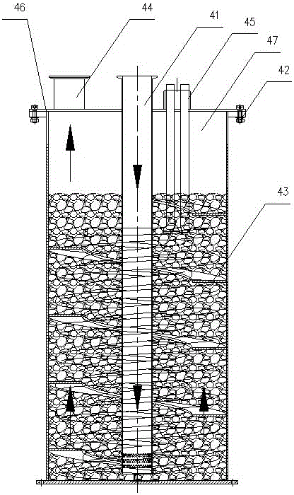
[0040] Example 1, such as Figure 1-3 As shown, a glove box with a purification system includes a main box body 1, a transition compartment 2, a glove operation port 3, a purification system 4, and a power system 6. The main box body 1, the transition compartment 2 are respectively provided with valves and are connected Air extraction and inflation interface; the purification system 4 includes a sealing cover 46, a purification cylinder 47, the sealing cover 46 and the purification cylinder 47 are connected by bolts 42; the purification cylinder 47 is fixedly provided with a main air passage 41 and a heater 45; the purification cylinder 47 The inner wall is provided with a spiral air passage 43, and the purification cylinder 47 is filled with purification materials.

Embodiment 2

[0041] In Embodiment 2, the clearance between the spiral air passage 43 and the bottom of the purification cylinder 47 in the embodiment 1 is 30 mm, and the upward angle of the spiral air passage is 15°.

Embodiment 3

[0042] Example 3, a method of using a glove box with a purification system:

[0043] The first step: purification system 4 reduction;

[0044] First connect the purification gas source 5, heat the purification material, heating time 100min; pass in reducing gas for 2 minutes, gas flow rate 10L / min; hold the pressure for 15 minutes and then vacuum for 15 minutes; then pass the gas flow automatic controller in two stages Reducing gas, the total time is 120min; the first stage is 30min, the gas flow rate is 10L / min; the second stage is 90min, the gas flow rate is 10L / min; the above procedure is cycled 4 times;

[0045] Step 2: Put in materials, experimental instruments or tools;

[0046] Open the outer door of the transition compartment 2 and put the materials to be placed on the material platform in the transition compartment 2, then open the inner door of the main box 1 and add the materials to be placed into the main box 1; close the main box 1. Transition cabin 2 doors;

[0047] The ...


PUM


Abstract

The invention relates to a glove box with a purification system and usage thereof. The glove box structurally comprises a main box body (1), a transition chamber (2), glove operation openings (3), the purification system (4) and a power system (6); the main box body (1) and the transition chamber (2) are respectively provided with a valve, and are connected with exhaust and charge ports; the glove box is characterized in that the purification system (4) comprises a sealing cover (46) and a purification cartridge (47), and the sealing cover (46) is connected with the purification cartridge (47) through bolts (42); a main air passage (41) and a heater (45) are fixedly arranged in the purification cartridge (47); a helical air passage (43) is arranged on the inner wall of the purification cartridge (47), and purification material fills the purification cartridge (47). The purification and regeneration effect of the glove box is good, and the utilization rate of the purification material is high.

Description

Technical field [0001] The invention belongs to the field of glove boxes, and particularly relates to a glove box with a purification system. Background technique [0002] At present, in the drying field, heating, decompression, and freezing methods are used to dry solids. The most common use is an oven, a vacuum oven, etc. The vacuum oven has a better drying effect. The application process of the vacuum oven is to place the drying material in a closed drying room, and use the vacuum system to draw a vacuum while heating the dried material continuously, so that the water inside the material diffuses to the surface through the pressure difference or the concentration difference, and the water molecules are on the material The process of obtaining enough kinetic energy on the surface to escape to the low-pressure space of the vacuum chamber after overcoming the mutual attraction between molecules, thereby being pumped away by the vacuum system. In the vacuum drying process, the pr...

Claims


Application Information

Patent Timeline
Patent Type & Authority Patents(China)
IPC IPC(8): B25J21/02
Inventor 肖森炎何亚登李国良
Owner 长沙天创粉末技术有限公司
Learn More