
Automatic Rolling Bending Die System and Its Application Method

A circular bending and automatic technology, applied in the field of automatic rolling circular bending die system, can solve the problems of easy occurrence of waste, high cost, low dimensional accuracy of products, etc. Effect

Active Publication Date: 2016-05-04
GUANGZHOU VOCATIONAL COLLEGE OF SCI & TECH
View PDF6 Cites 0 Cited by
  • Summary
  • Abstract
  • Description
  • Claims
  • Application Information

AI Technical Summary

Problems solved by technology

On the one hand, 3 to 4 sets of forming molds and 3 to 4 punching machines need to be used, and each set of molds and punching machines requires an operator to complete, the production cost is relatively high, and it cannot meet mass production
On the other hand, the more forming processes, the lower the dimensional accuracy of the product
even more waste
At the same time, in the current production of such round parts, the final workpiece is still manually stripped, and the workpiece is removed from the forming mandrel by manpower with the help of tools. On the one hand, the efficiency is low, and on the other hand, the workpiece is easy to be damaged.
The traditional processing method has many procedures, high cost, low efficiency, low dimensional accuracy, prone to waste products, and cannot realize automatic stripping

Method used

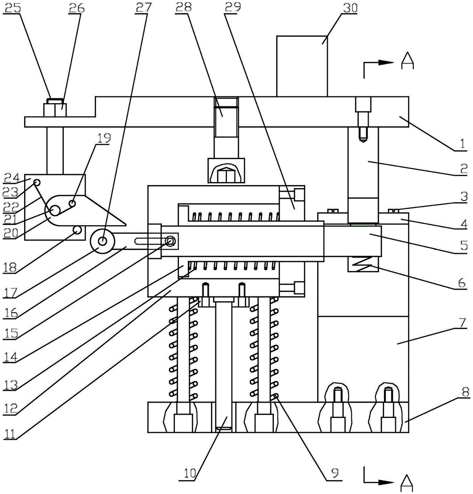
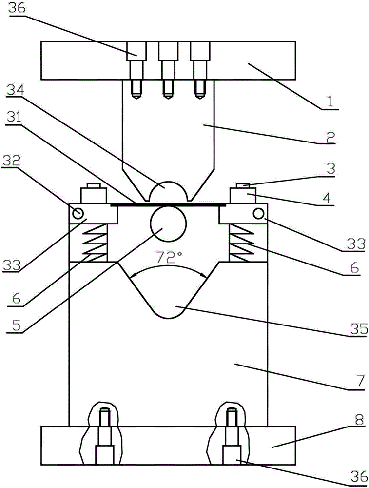
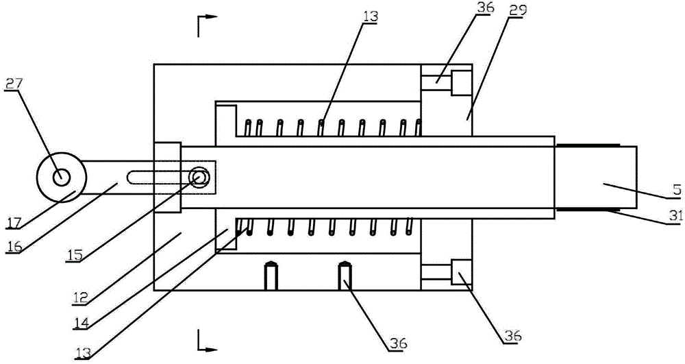

Image

  • Automatic Rolling Bending Die System and Its Application Method
  • Automatic Rolling Bending Die System and Its Application Method
  • Automatic Rolling Bending Die System and Its Application Method

Examples


Embodiment Construction

[0038] In order to facilitate the understanding of the present invention, the present invention will be described more fully below with reference to the associated drawings. Preferred embodiments of the invention are shown in the accompanying drawings. However, the present invention can be embodied in many different forms and is not limited to the embodiments described herein. On the contrary, these embodiments are provided to make the understanding of the disclosure of the present invention more thorough and comprehensive.

[0039] It should be noted that when an element is referred to as being “fixed” to another element, it can be directly on the other element or there can also be an intervening element. When an element is referred to as being "connected to" another element, it can be directly connected to the other element or intervening elements may also be present.

[0040]Unless otherwise defined, all technical and scientific terms used herein have the same meaning as ...


PUM

PropertyMeasurementUnit
angleaaaaaaaaaa

Abstract

The invention discloses an automatic rolling bending mould system and a use method thereof. The automatic rolling bending mould system comprises a first forming part, a second forming part, a spindle, a first driving device and at least two supporting parts, wherein the first driving device is used for driving the first forming part and the spindle to longitudinally move; the first forming part and the second forming part are respectively provided with a first groove part with a smooth inner wall and a second groove part with a smooth inner wall; an opening of the first groove part faces the opening of the second groove part; the supporting parts are hinged between the first forming part and the second forming part; a first elastic part is arranged between the supporting parts and the second forming part; the two supporting parts are arranged at an interval; the spindle is horizontally arranged in the gap between the two supporting parts and is located under a plane of the tops of the two supporting parts. The automatic rolling bending mould system provided by the invention has the advantages of few processing processes, low cost, high processing and production efficiency, high product precision and low reject rate.

Description

technical field [0001] The invention relates to the field of mechanical workpiece processing, in particular to an automatic rounding and bending die system and its application method. Background technique [0002] Such as figure 1 The round workpiece shown is very common in industrial structural parts, hardware structural parts, and household items. But the traditional processing method is to go through 3 to 4 processes to shape it. On the one hand, 3 to 4 sets of forming molds and 3 to 4 punching machines need to be used, and each set of molds and punching machines requires an operator to complete. The production cost is relatively high, and it cannot meet mass production. On the other hand, the more forming processes, the lower the dimensional accuracy of the product. There are even more waste products. At the same time, in the current production of this kind of rolled parts, the final workpiece is still manually stripped, and the workpiece is removed from the forming ...

Claims


Application Information

Patent Timeline
Patent Type & Authority Patents(China)
IPC IPC(8): B21D5/10B21D37/10B21D37/12B21D43/00B21D45/04
CPCB21D5/10B21D37/10B21D37/12B21D43/003B21D45/04
Inventor 邓汝荣曾蕾
Owner GUANGZHOU VOCATIONAL COLLEGE OF SCI & TECH
Learn More