Seismic isolation structure for heavy objects, and seismic isolation method
A technology of heavy objects and pressurized plates, which is used in basic structural engineering, shock absorbers, engine frames, etc., to achieve simple installation work and improve the effect of anti-vibration
- Summary
- Abstract
- Description
- Claims
- Application Information
AI Technical Summary
Problems solved by technology
Method used
Image


Examples
Embodiment 1
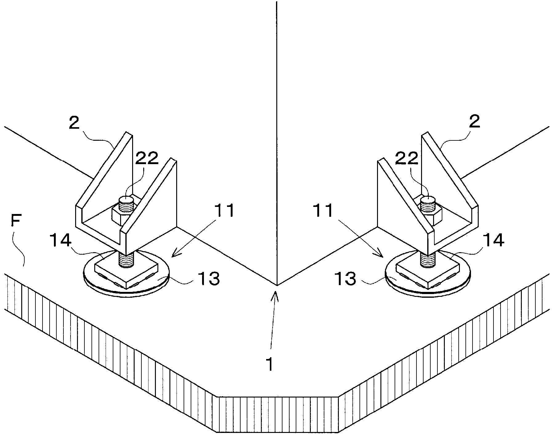
[0055] Such as figure 1 and 2 As shown, the seismic isolation structure 11 of Embodiment 1 is installed between the machine 1 as a heavy object and the ground F. As shown in FIG. The machine 1 includes a plurality of legs 2 , while the isolation structure 11 includes a mechanism for adjusting the height of the legs 2 relative to the ground F. As shown in FIG. The shock-isolation structure 11 is provided with: a shock-absorbing pad 12 (referring to figure 2 ), the vibration damping pad is set on the ground F; the pressure plate 13, the pressure plate 13 squeezes the vibration damping pad 12; plate 13.
[0056] Such as figure 2 and 3 As shown, the vibration-damping pad 12 is composed of a gel-like elastic body 15 having elastic-viscosity and a support body 16 capable of plastic deformation. The gel-like elastic body 15 is formed in a circular shape from a transparent or translucent polymer material. Adhesive layers 15a and 15b (see image 3 a) Provided on the bottom and...
Embodiment 2
[0064] exist Figure 5 and 6 In the shown shock-absorbing structure 211 , the base 21 of the holder 14 is clamped to the pressure plate 13 by the four arcuate members 28 with the vibration-proof rubber 29 interposed between the base 21 and the pressure plate 13 . The arcuate parts 28 are assembled to cross each other, and are fastened with bolts 30 to bolts 31 provided on the pressing plate 13 . Bonded to the lower surface of the base 21 is an intermediate plate 32 provided with a restricting wall 34 formed along the periphery of the intermediate plate 32 for blocking the caulking compound 33 . In addition, the anti-vibration rubber 29 is disposed within the restricting wall 34, so that the upper and lower two-layer elastic members composed of the anti-vibration rubber 29 and the vibration-damping pad 12 can provide improved shock absorption.
Embodiment 3
[0066] according to Figure 7 and 8 In the shown shock-absorbing structure 311 , the holder 14 includes: a cylindrical member 36 surrounding the leg 6 of the weight 5 , and the lateral movement of the leg 6 on the pressing plate 13 is restricted by the cylindrical member 36 . The legs 6 are attached to the weight 5 (only part of which is shown) in a manner that allows the height of the legs 6 to be adjusted with screws 7 , and the legs 6 are also removably inserted into the cylindrical member 36 . Therefore, the shock-absorbing structure 311 of Embodiment 3 is preferably applicable to heavy objects that are relatively light in weight and need to be transported, such as tool tables and display cabinets. Note that, in the illustrated vibration-damping pad 12 , a single support body 16 and a single ring 12 are embedded at the center of the gel-like elastic body 15 .
PUM
 Abstract
Description
Claims
Application Information
 - Generate Ideas
- Intellectual Property
- Life Sciences
- Materials
- Tech Scout
- Unparalleled Data Quality
- Higher Quality Content
- 60% Fewer Hallucinations
Browse by: Latest US Patents, China's latest patents, Technical Efficacy Thesaurus, Application Domain, Technology Topic, Popular Technical Reports.
© 2025 PatSnap. All rights reserved.Legal|Privacy policy|Modern Slavery Act Transparency Statement|Sitemap|About US| Contact US: help@patsnap.com