Aircraft brake assembly

A braking assembly, aircraft technology, applied in aircraft braking arrangements, aircraft parts, brakes, etc., to achieve the effects of simple structural components, simplified raw materials, and reduced weight

Active Publication Date: 2015-01-28
MESSIER DOWTY
View PDF4 Cites 1 Cited by
  • Summary
  • Abstract
  • Description
  • Claims
  • Application Information

AI Technical Summary

Problems solved by technology

Landing gear can thus be made lighter and less complex

Method used


Image

  • Aircraft brake assembly
  • Aircraft brake assembly
  • Aircraft brake assembly

Examples


Embodiment Construction

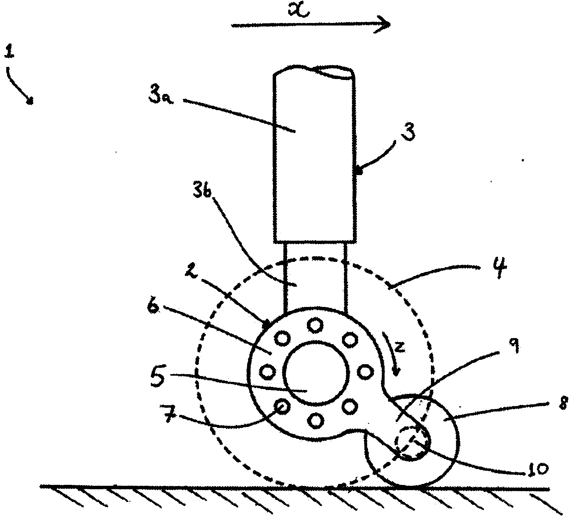
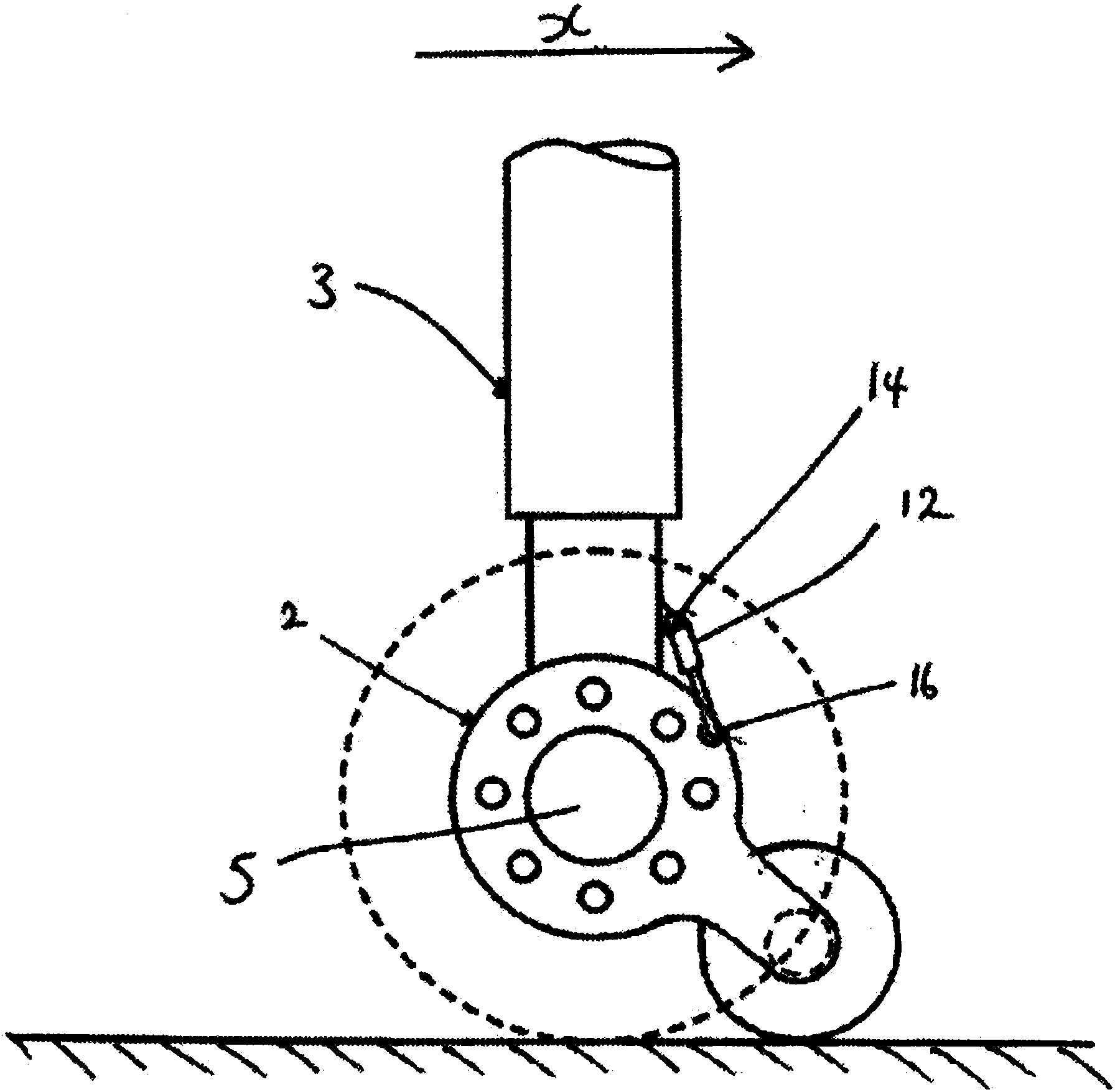
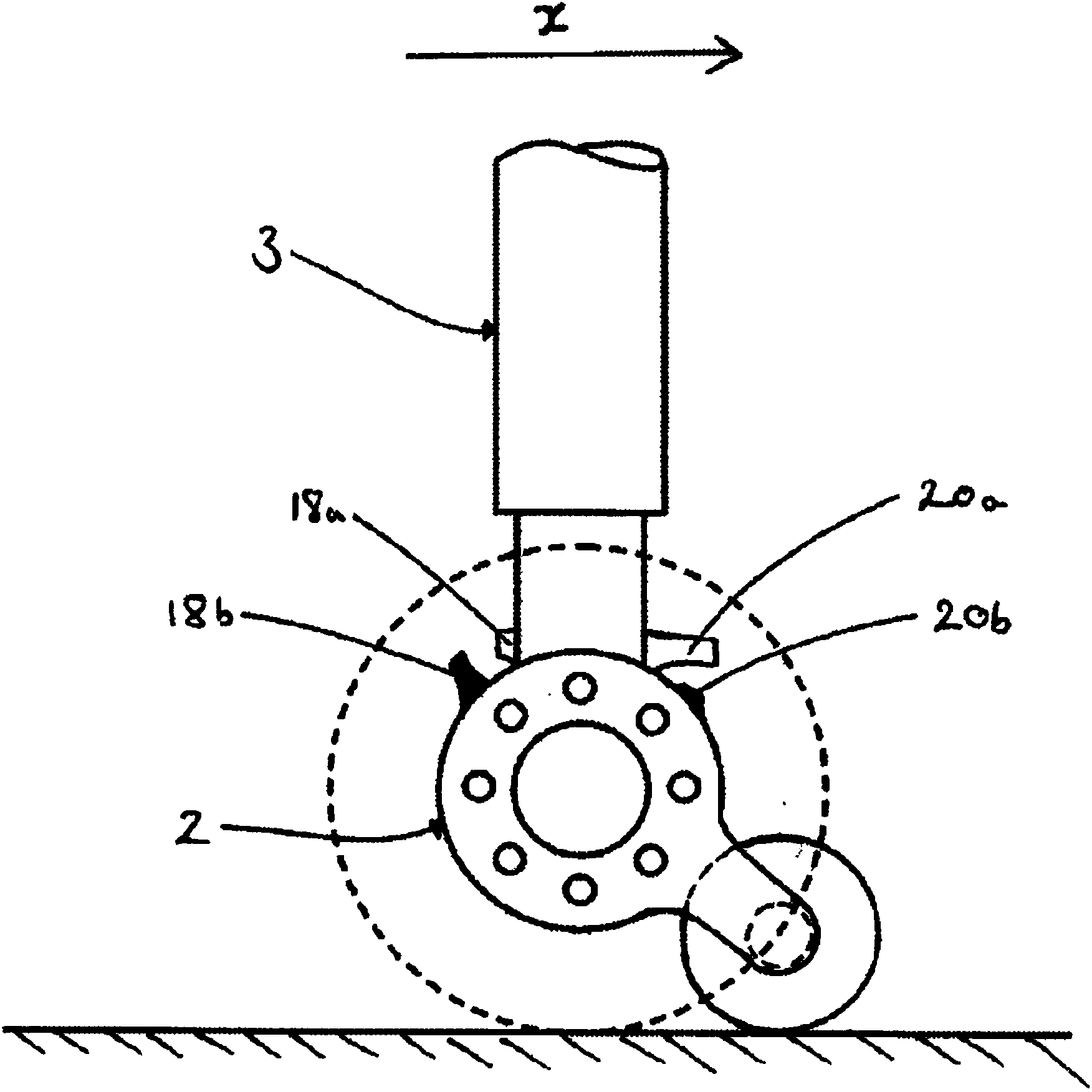
[0020] figure 1 An aircraft landing gear 1 comprising a braking assembly 2 according to an embodiment of the invention is shown, the aircraft landing gear 1 being on the ground. The aircraft landing gear 1 comprises a telescoping support leg 3 comprising an upper part 3a and a lower part 3b. Embodiments described herein include telescoping support legs. However, those skilled in the art will appreciate that the invention is equally applicable to aircraft landing gear comprising fixed undercarriage legs. In the embodiment shown, the undercarriage is a main undercarriage having a single pair of main wheels 4 at either end of the axle 5 , which may form part of the lower portion 3b of the telescoping support leg 3 . Those skilled in the art will appreciate that this design can be implemented on a main landing gear having a bogie beam with two or more pairs of tires with the mechanisms described herein incorporated into the wheels and one or more of the associated brakes. The ...


PUM


Abstract

Aircraft brake assembly having a main wheel 4, 36a, 36b, rotatably mounted on a support leg 3, 32 of a landing gear and a brake assembly 2, 38, 40 comprising a first sub-assembly 38a, 40a fixed to the wheel and a second sub assembly 6, 38b, 40b movably mounted on the support leg 3; and a ground reaction wheel 8, 42 mounted to the second sub-assembly 6, 38b, 40b, preferably via brake arm 9, wherein on application of the brake 2, 38, 40 the first and second sub-assemblies engage and the ground reaction wheel 8, 42 transfers a braking force from the second sub-assembly 6, 38b, 40b to the ground. Movement of the second sub assembly relative to the support leg may be inhibited, preferably by damper(s), (12, fig 2) or stops (18a, 18b, 20a, 20b, fig 3). The second sub assembly may be biased into position, either by a spring or an actuator.

Description

Background technique [0001] In typical aircraft landing gear, multi-plate brake assemblies are mounted on the wheels of the aircraft to effect braking after the aircraft has landed on the runway. Typically, these brake assemblies consist of a set of disc brakes permanently affixed to the wheel on which the wheel is mounted, and a set of brake shoes affixed to a leg or axle of the landing gear. When the brakes are applied, the pads press against the disc brakes, creating friction that resists the rotation of the wheels, slowing the aircraft down. [0002] In these arrangements, the brake assembly attached to the gear leg or shaft is prevented from rotating by means of a brake lever or brake flange (a series of bolts passing through a mount) integral with the gear leg. Thus, the torque generated when the brakes are applied is transmitted from the brakes to the brake levers and / or bolts and reacted through the landing gear. This subjects the landing gear components to a great d...

Claims


Application Information

Patent Timeline
Patent Type & Authority Applications(China)
IPC IPC(8): B64C25/34B64C25/42F16D55/36
CPCB64C25/34B64C25/42B60T8/1703B64C25/36B64C25/62
Inventor 克里斯·格林扬·西蒙奥克斯
Owner MESSIER DOWTY
Why Eureka
Try Eureka