
Communicating tube used for high-capacity separating wiring

A separate, large-capacity technology, applied in the field of communication tubes, can solve the problems that affect the service life of cables, the form is not ideal, and the heat dissipation effect is not very good, so as to achieve the effect of improving service life, good heat dissipation effect and increasing quantity

Inactive Publication Date: 2015-01-28
CHONGQING YICHU MACHINERY
View PDF4 Cites 0 Cited by
  • Summary
  • Abstract
  • Description
  • Claims
  • Application Information

AI Technical Summary

Problems solved by technology

In order to increase the number of internal wiring, the existing communication tubes generally adopt the method of partitions. For example, a partition is set in the communication tube, and the partition divides the internal space of the communication tube into two equal-volume areas, and then separates each Although this type of method increases the number of internal wiring of the communication tube to a certain extent, the form is not ideal. In addition, because the internal cables overlap each other, the heat dissipation effect is not very good, which affects the service life of the cable

Method used


Image

  • Communicating tube used for high-capacity separating wiring
  • Communicating tube used for high-capacity separating wiring
  • Communicating tube used for high-capacity separating wiring

Examples


Embodiment Construction

[0021] In order to make the technical means, creative features, goals and effects achieved by the present invention easy to understand, the present invention will be further described below in conjunction with specific illustrations.

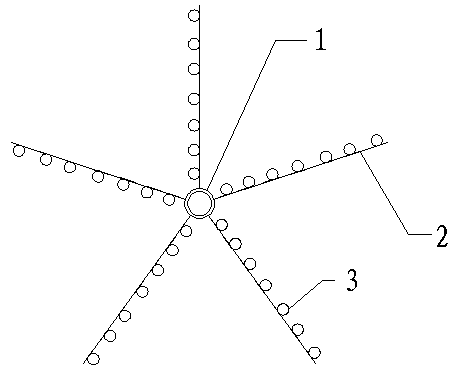
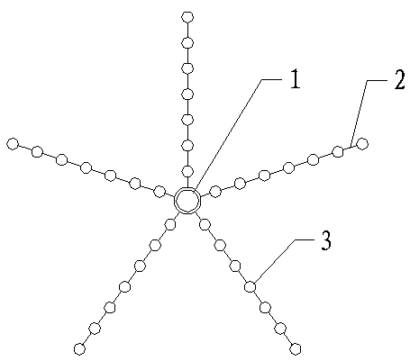
[0022] see Figure 1 to Figure 4 , a communication pipe for large-capacity separated wiring, including a pipe body, a threading device is arranged in the pipe body, the threading device has an intermediate pipe, and several sets of sub-threading structures are arranged on the intermediate pipe along the axial direction, the The sub-threading structure includes several support rods, the support rods are arranged in an annular array on the intermediate pipe, and several sub-wire tubes are arranged on each support rod, and the sub-wire tubes are arranged along the length direction of the support rods. A fastening device is provided at both ends of the intermediate pipe, and the fastening device includes a fixed ring sleeved on the end of the interm...


PUM


Abstract

The invention discloses a communicating tube used for high-capacity separating wiring. The communicating tube comprises a tube body. A threading device is arranged in the tube body and provided with a middle tube. The middle tube is provided with a plurality of subsidiary threading structures axially arranged. Each subsidiary threading structure comprises a plurality of supporting rods. The supporting rods are arrayed on the middle tube in an annular mode. Each supporting rod is provided with a plurality of subsidiary spools. The subsidiary spools are arrayed in the length direction of the supporting rods. The two ends of the middle tube are each provided with a fastening device. Each fastening device comprises a fixing ring arranged at the end of the middle tube in a sleeving mode. Each fixing ring is provided with at least two fixing rods in the circumferential direction. A fastening head is arranged at the end of each fixing rod. The distance from the fastening heads to the axis of the middle tube is not smaller than the inner diameter of the tube body. As the threading device is arranged in the communicating tube, the number of wires arranged in the communicating tube can be increased; meanwhile, as the subsidiary spools of the threading device are mutually spaced, mutual influence of cables penetrating through the communicating tube is small, the heat dissipating effect is good, and the service life of the cables is prolonged.

Description

technical field [0001] The invention relates to a communication tube for large-capacity separated wiring. [0002] Background technique [0003] The communication tube is an indispensable accessory in the daily embedding operation, which plays a protective role for the cable. In order to increase the number of internal wiring, the existing communication tubes generally adopt the method of partitions. For example, a partition is set in the communication tube, and the partition divides the internal space of the communication tube into two equal-volume areas, and then separates each Although this type of method increases the number of internal wiring of the communication tube to a certain extent, the form is not ideal. In addition, because the internal cables overlap each other, the heat dissipation effect is not very good, which affects the service life of the cable. [0004] Contents of the invention [0005] The object of the present invention is to solve the above-ment...

Claims


Application Information

Patent Timeline
Patent Type & Authority Applications(China)
IPC IPC(8): H02G3/04
Inventor 钟伟
Owner CHONGQING YICHU MACHINERY
Learn More