
Faraday rotating lens irrelevant to wavelength and temperature

A Faraday rotating mirror and Faraday rotator technology, applied in nonlinear optics, instruments, optics, etc., can solve the problem that broadband wavelength and large temperature range cannot be effective at the same time, and achieve the effect of eliminating the effect of rotation angle dispersion and temperature-related effects

Inactive Publication Date: 2015-01-28
OPSMITH TECH
View PDF2 Cites 5 Cited by
  • Summary
  • Abstract
  • Description
  • Claims
  • Application Information

AI Technical Summary

Problems solved by technology

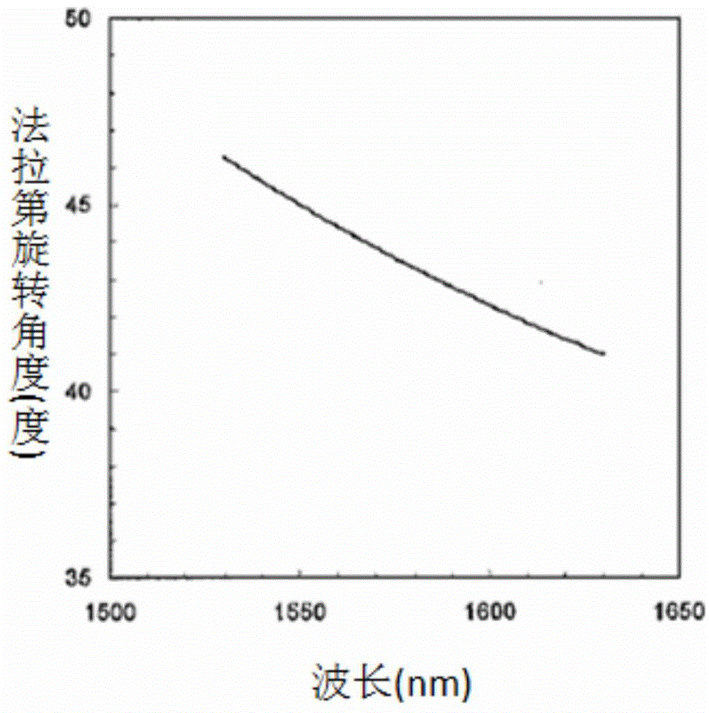
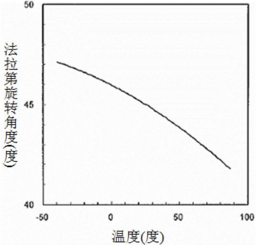
However, due to the inherent rotation angle dispersion and temperature-dependent characteristics of Faraday rotation crystal materials, the above compensation methods cannot be effective for broadband wavelengths and large temperature ranges at the same time.

Method used


Image

  • Faraday rotating lens irrelevant to wavelength and temperature
  • Faraday rotating lens irrelevant to wavelength and temperature
  • Faraday rotating lens irrelevant to wavelength and temperature

Examples


Embodiment 1

[0030] Figure 5 The wavelength- and temperature-independent Faraday rotating mirror includes a single-mode single-fiber collimator 11, a Nomarski prism 12, whose optical axis X1 is consistent with the x-axis, and whose optical axis X2 is in the y-z plane, a Faraday Rotator 13, a dielectric optical thin film plane reflector 14.

[0031] Figure 5The light 100 emitted from the single-mode single-fiber collimator 11 is transmitted along the z-axis of the Cartesian coordinate system, and when it hits the Nomarski prism 12, it is first divided into two beams of linearly polarized ordinary light 111 and non-linearly polarized light whose polarization directions are perpendicular to each other. Ordinary light 121 converges when passing through the two wedge-angle interfaces of the prism, passes through the Faraday rotator 13, and the vibrating plane rotates about 45 degrees to become light beams 112 and 122, and intersect on the plane mirror 14, the light beams 112 and 122 are resp...

Embodiment 2

[0036] Figure 9 The wavelength- and temperature-independent Faraday rotator in contains a single-mode single-fiber collimator 21, a polarizing beam shifter 22 whose optical axis X3 is in the y-z plane, and a Wollaston prism 23 whose optical axis X4 is parallel to the x-axis, the optical axis X5 is in the y-z plane, and its edges are parallel to the x-axis, a Faraday rotator 24 , and a dielectric optical film flat mirror 25 .

[0037] Figure 4 The light 300 emitted from the single-mode single-fiber collimator 21 is transmitted along the z-axis of the Cartesian coordinate system, and is incident on the polarized beam shifter 22 to be divided into two beams of linearly polarized extraordinary light 311 and ordinary light whose polarization directions are perpendicular to each other. The light 321 converges after passing through the Wollaston prism 23, passes through the Faraday rotator 24, and the vibrating plane rotates about 45 degrees to become two converging beams of light...


PUM


Abstract

The invention provides a faraday rotating lens capable of eliminating relevance between a rotating angle of the faraday rotating lens and the wavelength and temperature. The faraday rotating lens is characterized in that a polarized light component, in the rotating angle dispersion direction, with the 90-degree deviated rotating angle after the action of the faraday rotating device is eliminated, so the rest light in each wavelength can be positioned in the identical single-direction line polarization state, so the light rotating angle change of the faraday rotating lens caused by wavelength and temperature relevance of the faraday rotating device can be eliminated, and the polarization state of the output light of the faraday rotating lens is irrelevant to the wavelength and the temperature. The faraday rotating lens has the advantages that the influence on the rotating angle dispersion and the temperature of the faraday rotating lens caused by any kinds of optically active crystals can be eliminated, and the faraday rotating lens is applicable to any occasions using faraday optically active crystals.

Description

technical field [0001] The invention belongs to the field of optical fiber sensing and optical fiber communication, and more specifically relates to a Faraday rotating mirror that eliminates the correlation between the rotation angle of the Faraday rotating mirror and the wavelength and temperature. Background technique [0002] In order to achieve high resolution in optical signal demodulation, interferometric demodulation methods are generally used, and the development of optical fiber interferometer is a key technology. Polarization-maintaining fiber is expensive, and the polarization-maintaining coupler is not perfect in some key technologies, which limits its application. Due to the birefringence effect of ordinary single-mode fiber, the polarization state of the two arms of the interferometer will change randomly, resulting in a change in the visibility of the output interference signal. This is the polarization-induced signal fading effect. [0003] When optical sign...

Claims


Application Information

Patent Timeline
IPC IPC(8): G02F1/09
CPCG02F1/09
Inventor 陈思思
Owner OPSMITH TECH
Learn More