
Coal-fired unit and gas turbine combined power generation system

A technology for gas turbines and coal-fired units, which is applied in joint combustion mitigation, machine/engine, mechanical equipment, etc., can solve the problems of low energy utilization efficiency of exhaust flue gas, low thermal cycle efficiency, large heat loss, etc. The effect of energy utilization efficiency, utilization rate improvement, and power generation efficiency improvement

Active Publication Date: 2016-02-10
HUADIAN ELECTRIC POWER SCI INST CO LTD
View PDF9 Cites 0 Cited by
  • Summary
  • Abstract
  • Description
  • Claims
  • Application Information

AI Technical Summary

Problems solved by technology

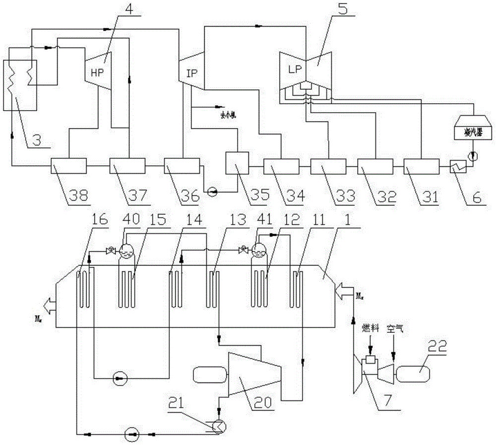
[0004] In order to solve the deficiencies in the prior art of low energy utilization efficiency of gas turbine exhaust gas, low thermal cycle efficiency, large heat loss, and low economic efficiency, the present invention provides a coal-fired unit and gas turbine combined power generation system, including Coal-fired units, gas turbines, waste heat boilers and feed water heaters, the coal-fired units include coal-fired boilers, steam turbines, condensers, shaft seal heaters, low-pressure heater systems, deaerators, high-pressure heater systems, the The waste heat boiler is connected to the flue gas outlet of the gas turbine, the feedwater heater is integrated in the waste heat boiler, the high pressure heater system is provided with a high pressure heater outlet bypass, and the high pressure heater outlet bypass is connected to the One end of the feed water heater, the other end of the feed water heater is connected to the coal-fired boiler

Method used


Image

  • Coal-fired unit and gas turbine combined power generation system
  • Coal-fired unit and gas turbine combined power generation system
  • Coal-fired unit and gas turbine combined power generation system

Examples


Embodiment Construction

[0039]The present invention will be described in detail below in conjunction with the accompanying drawings.

[0040] figure 1 The flow chart of the combined cycle sub-system of conventional million coal-fired units and conventional gas turbines without heat and mass exchange is shown. Coal-fired units include generators, coal-fired boilers 3, steam turbines, condensers, low-pressure heater systems, deaerators, high-pressure heater systems, and auxiliary systems such as pumps and pipelines, which are connected in sequence to form a closed cycle system. Gas turbine combined cycle The system includes a gas turbine 7, a generator, and a lower power station. The lower power station includes a waste heat boiler 1, a generator, a lower steam turbine 20, a lower condenser 21, and auxiliary systems such as pumps and pipelines to form a closed circulation system. The waste heat boiler and gas turbine 7 flue gas The outlets are connected, and the flue gas exhausted by the gas turbine 7...


PUM


Abstract

The invention relates to a coal-fired unit and gas turbine combined type power generation system, and belongs to the field of combined power generation. The coal-fired unit and gas turbine combined type power generation system comprises a coal-fired unit, a gas turbine, a residual heat boiler and a water feeding heater, wherein the water feeding heater is integrated in the residual heat boiler, a high-pressure heater system of the coal-fired unit is provided with an outlet bypass, and is connected with the water feeding heater, the other end of the water feeding heater is connected with a coal-fired boiler of the coal-fired unit, a shaft seal heater of the coal-fired unit is provided with a bypass, condensate enters the residual heat boiler through the bypass, and is heated to form steam, and then the steam is supplemented into a steam turbine of the coal-fired unit. The coal-fired unit and gas turbine combined type power generation system has the advantages that the heat circulating efficiency is greatly improved, the utilization rate of energy source is improved, the coal consumption of power generation enterprises is reduced, and the energy-saving and emission-reduction purposes are realized.

Description

technical field [0001] The invention relates to a combined power generation system, in particular to a combined power generation system of a coal-fired unit and a gas turbine. Background technique [0002] The flue gas exhausted by gas turbines has high energy. The existing form of energy utilization is to use a waste heat boiler and a lower steam turbine to form a combined cycle lower power station, but the efficiency of the entire combined cycle lower steam turbine power station is low. The cycle thermal efficiency of the steam turbine in the lower power station is about 33%, and the thermal efficiency of the F-class gas turbine combined cycle lower power station steam turbine cycle is about 35%. Most of the energy loss is at the cold end, and the efficiency is relatively low, while the efficiency of the general waste heat boiler is about 84%. The lower power station efficiency of the entire gas-steam combined cycle is about 27% to 29%, that is, if there is 100% energy in ...

Claims


Application Information

Patent Timeline
Patent Type & Authority Patents(China)
IPC IPC(8): F01K23/10F01K17/02
CPCY02E20/14Y02E20/16
Inventor 谢大幸常浩石永锋郝建刚徐婷婷郑健李飞飞王健
Owner HUADIAN ELECTRIC POWER SCI INST CO LTD
Learn More