Laser dazzling helmet

A helmet, dazzling technology, applied in the direction of light source, electric light source, point light source, etc., can solve the problems of large light divergence angle, poor endurance, neck injury of users, etc., achieve high spectral brightness, good beam quality, reduce The effect of weight

Inactive Publication Date: 2015-01-21
大连淡宁实业发展有限公司
View PDF5 Cites 1 Cited by
  • Summary
  • Abstract
  • Description
  • Claims
  • Application Information

AI Technical Summary

Problems solved by technology

[0005] Existing dazzling helmets use high-power light-emitting devices such as strong lights and strobe lights or LED arrays as dazzling light sources, which have the advantages of large weight, high power consumption, and poor battery life; and poor long-distance dazzling effects
Mainly, high-voltage arc lamps such as mercury lamps and xenon lamps are used as light sources for high-voltage lamps and flashing lamps. However, the luminous efficiency of arc lamps is very low, and the required power supply is large, which leads to high power consumption of traditional dazzling anti-riot helmets. Poor; at the same time, the light divergence angle of strong lights, flashing lights and LEDs is large, and the luminous intensity of a single LED is not enough to require LED arrays or area arrays to achieve the required light intensity, so a large reflective bowl or beam shaping system is required Converging light, this traditional optical structure will cause a loss of light energy of more than 10 meters and the dazzling effect is not good; the overall volume and structure of the arc lamp is large, resulting in the heavy weight of the traditional dazzling helmet, which is not easy to wear for a long time. Helmets can cause neck injuries to users
Therefore, the practicability of traditional blinding helmets is poor and fails to be equipped in large quantities

Method used


Image

  • Laser dazzling helmet
  • Laser dazzling helmet

Examples


Embodiment Construction

[0023] The present invention will be described in detail below with reference to the accompanying drawings and examples.

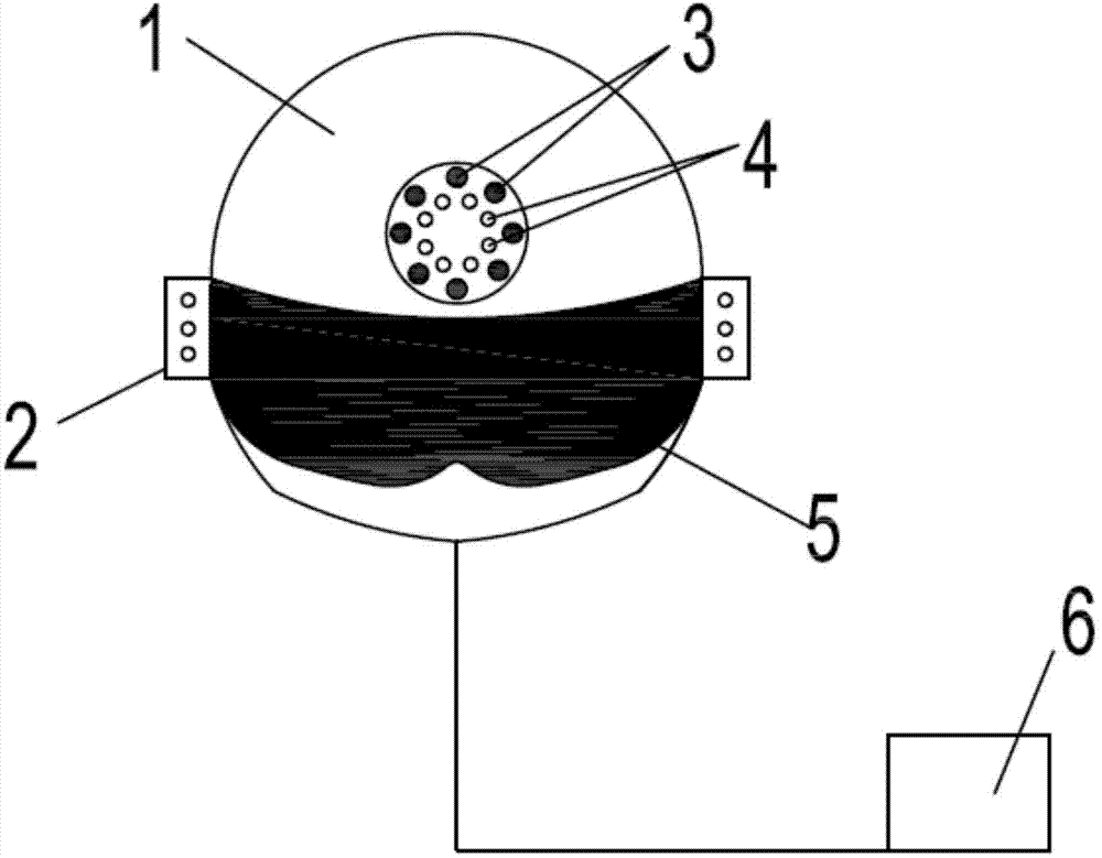
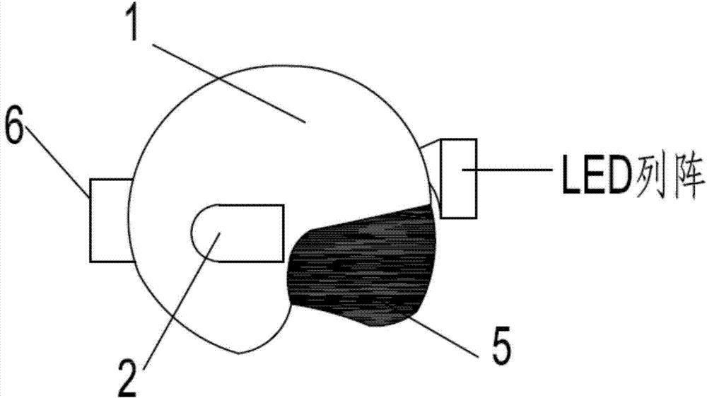
[0024] as attached figure 1 and 2 As shown, the present invention provides a laser dazzling helmet, including a helmet body 1, a laser source 2, a first LED array 3, a second LED array 4, a protective mask 5 and a power supply 6;

[0025] Wherein, the laser source 2 uses a semiconductor laser or a small all-solid-state laser of the Nd:YVO4 optical glue KTP system pumped by a semiconductor laser; the emission wavelength of the laser source is 500-560nm or 600-670nm;

[0026] The first LED array 3 is composed of green or red LEDs and is responsible for dazzling at short distances; the second LED array 4 is composed of white LEDs and can be used for daily lighting or anti-riot dazzling; the first LED array 3 and the wavelength of the second LED array 4 are 500-560nm, 600-670nm or white light;

[0027] Its overall connection relationship is: the laser sourc...


PUM

PropertyMeasurementUnit
Luminous wavelengthaaaaaaaaaa
Wavelengthaaaaaaaaaa

Abstract

The invention discloses a laser dazzling helmet, and belongs to the field of security protection and the photoelectric technology. The helmet comprises a helmet body, at least one laser source, a first LED array, a second LED array, a protective mask and a power supply. The laser source is arranged on the side of the helmet body, the first LED array and the second LED array are concentrically arranged in the front of the helmet body, the first LED array is composed of green light or red light LEDs, the second LED array is composed of white light LEDs, the protective mask and the helmet body are movably connected, an attenuation film is attached to the surface of the protective mask, the laser source, the first LED array and the second LED array 4 are connected with the power supply through wires, and the power supply is fixedly connected with the rear side of the helmet body. Long-distance dazzling is carried out on mobs by means of the laser source so that the mobs can lose vision temporarily, short-distance dazzling is carried out through the LED arrays so that the mobs can not look at the police directly or effective attack, and the police can quickly attack or guard.

Description

technical field [0001] The invention relates to an anti-riot device, in particular to a helmet, which belongs to the field of security and photoelectric technology. Background technique [0002] The function of a large number of police anti-riot equipment currently equipped in our country is too single, such as simple shields, batons, and anti-riot forks. [0003] On March 1, 2014, the appalling Kunming massacre occurred in Kunming, my country. Five thugs with knives killed more than 180 innocent citizens in a relatively short period of time. Among them, a deputy director of a police station died heroically in the process of using a riot fork to resist riots, highlighting the inadequacy of our country's police anti-riot equipment in fighting sudden violent terrorist incidents. [0004] Using visible light to dazzle mobs and make them temporarily blind and lose their attack power is currently internationally recognized as a method of anti-riot with the least harm to human bo...

Claims


Application Information

Patent Timeline
IPC IPC(8): F41H1/04F21S8/00F21V19/00F21V23/00F21V33/00F21Y101/02
Inventor 王戈许江珂郑帅
Owner 大连淡宁实业发展有限公司
Why Eureka
Try Eureka