
Balloon catheter having a textured member for enhancing balloon for stent retention

a textured member and balloon catheter technology, applied in the field of balloon catheters, can solve the problem of balloon falling out of position during balloon inflation, and achieve the effect of improving the ability of the balloon

Inactive Publication Date: 2007-10-18
ABBOTT CARDIOVASCULAR
View PDF2 Cites 24 Cited by
  • Summary
  • Abstract
  • Description
  • Claims
  • Application Information

AI Technical Summary

Benefits of technology

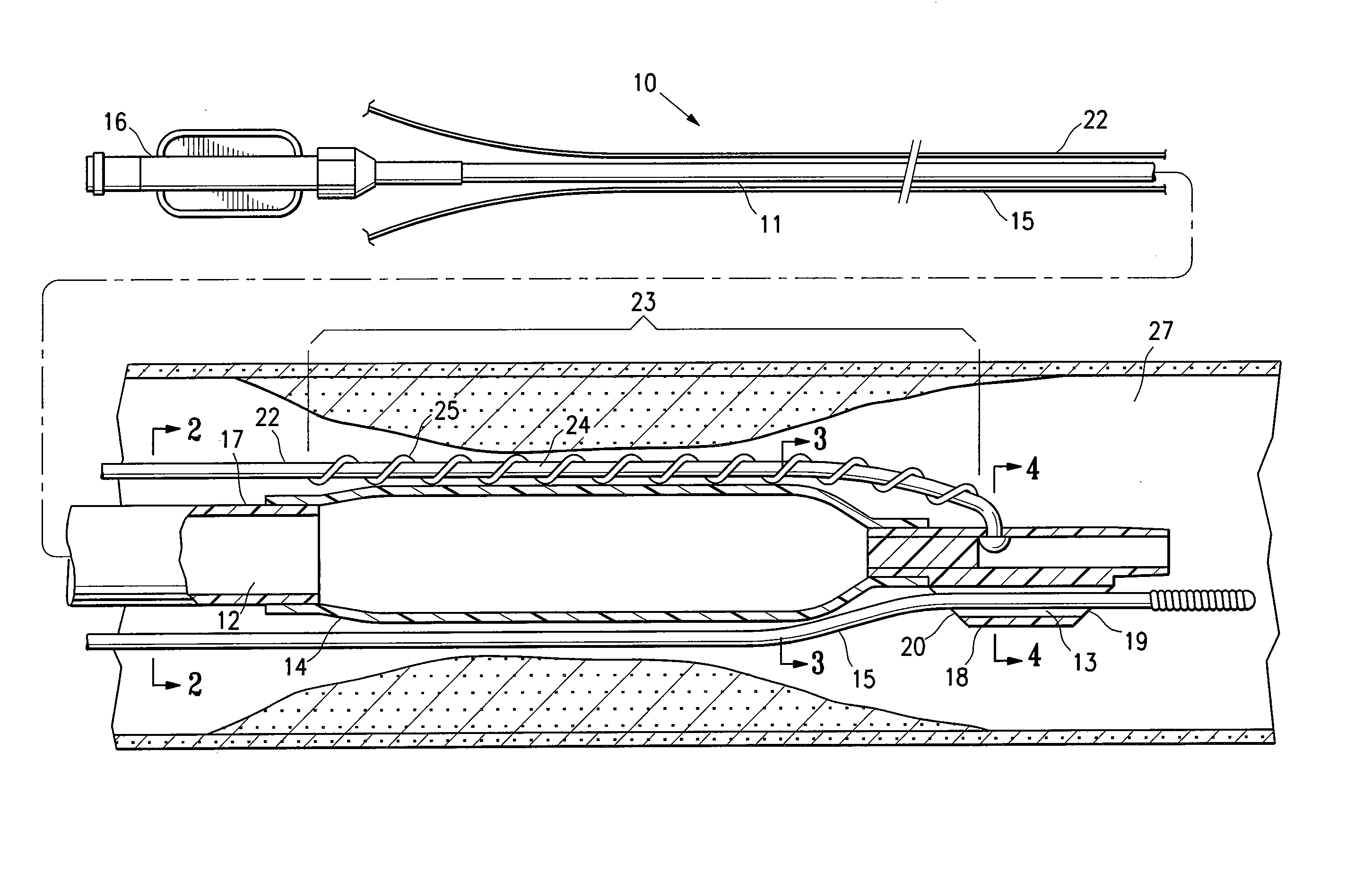
[0005] The invention is directed to a balloon catheter having at least one advancement wire with a distal end section secured to a distal tip section of the catheter, and with a textured section extending along the outer surface of at least a portion of an inflatable section of the catheter balloon. The textured section of the advancement wire preferably improves the ability of the balloon to remain in position in the patient's body lumen during inflation of the balloon to perform a medical procedure such as balloon angioplasty or stent touch-up.
[0008] With the advancement wire extending external to the catheter balloon, the textured section is exposed along the outer surface of the balloon, to thereby enhance the frictional engagement of the balloon against the vessel wall during inflation of the balloon to dilate a stenosis. As a result, any tendency of the balloon to slip out of position in the patient's body lumen is prevented or inhibited by the catheter of the invention. Additionally, the textured section provides improved control over the dissection of a stenosis as the balloon inflates against the stenosis. Specifically, the textured section provides focal stresses as it cuts into the stenosis, thereby controlling the resulting dissection planes. However, unlike a cutting balloon having a blade along the outer surface of the balloon, the texture section in a presently preferred embodiment has a rounded outer surface which avoids substantial areas of injury to the vessel as the catheter is positioned therein. Additionally, the textured section provides regions of high and low stress which in one embodiment limits vessel damage to only the high stress areas.
[0009] In one embodiment in which the balloon is inflated within a previously expanded stent, the textured section is configured to mesh with the stent. Specifically, the longitudinally spaced apart projections or peaks of the textured section have a spacing therebetween which is configured to accommodate the stent struts. For example, with a conventional stent design comprising a series of connected rings, the stent strut forming a ring fits within the longitudinal space between adjacent projections or peaks of the textured section. Thus, during dilatation of a stenosed region within a previously implanted stent (typically referred to as “in-stent restenosis”), or during a stent touch-up in which the balloon further expands a partially expanded stent in the patient's body lumen, the balloon catheter of the invention does not slip longitudinally out of position during inflation of the balloon, due to the textured section of the advancement wire. It is important to match the length of the inflated balloon to the length of the stent in such procedures, to avoid unintended injury to the patient's vessel which can result when sections of the balloon over-inflate against the vessel wall. As a result, the balloon catheter of the invention prevents or inhibits such injury by inhibiting an otherwise well matched balloon from longitudinally slipping out of position within the stent during inflation of the balloon.
[0011] In the embodiment in which the textured section is formed by a wound wire member, characteristics such as the pitch of the wound wire can be easily selected and manufactured to mesh with any of a variety of commercially available stents. The stiffness resulting from the wound wire will increase as the pitch of the wound wire decreases. Consequently, in one embodiment in which the pitch of the wound wire is relatively low, the wound wire is preferably formed of a relatively flexible material such as a polymer or a superelastic material such as NiTi alloy (Nitinol), to mitigate the increased stiffness that would otherwise result from the low pitch wound wire formed of a less flexible material such as stainless steel.

Problems solved by technology

However, one difficulty has been the tendency of the balloon to slip out of position during inflation of the balloon, a problem referred to as “watermelon seeding”.

Method used


Image

  • Balloon catheter having a textured member for enhancing balloon for stent retention
  • Balloon catheter having a textured member for enhancing balloon for stent retention
  • Balloon catheter having a textured member for enhancing balloon for stent retention

Examples


Embodiment Construction

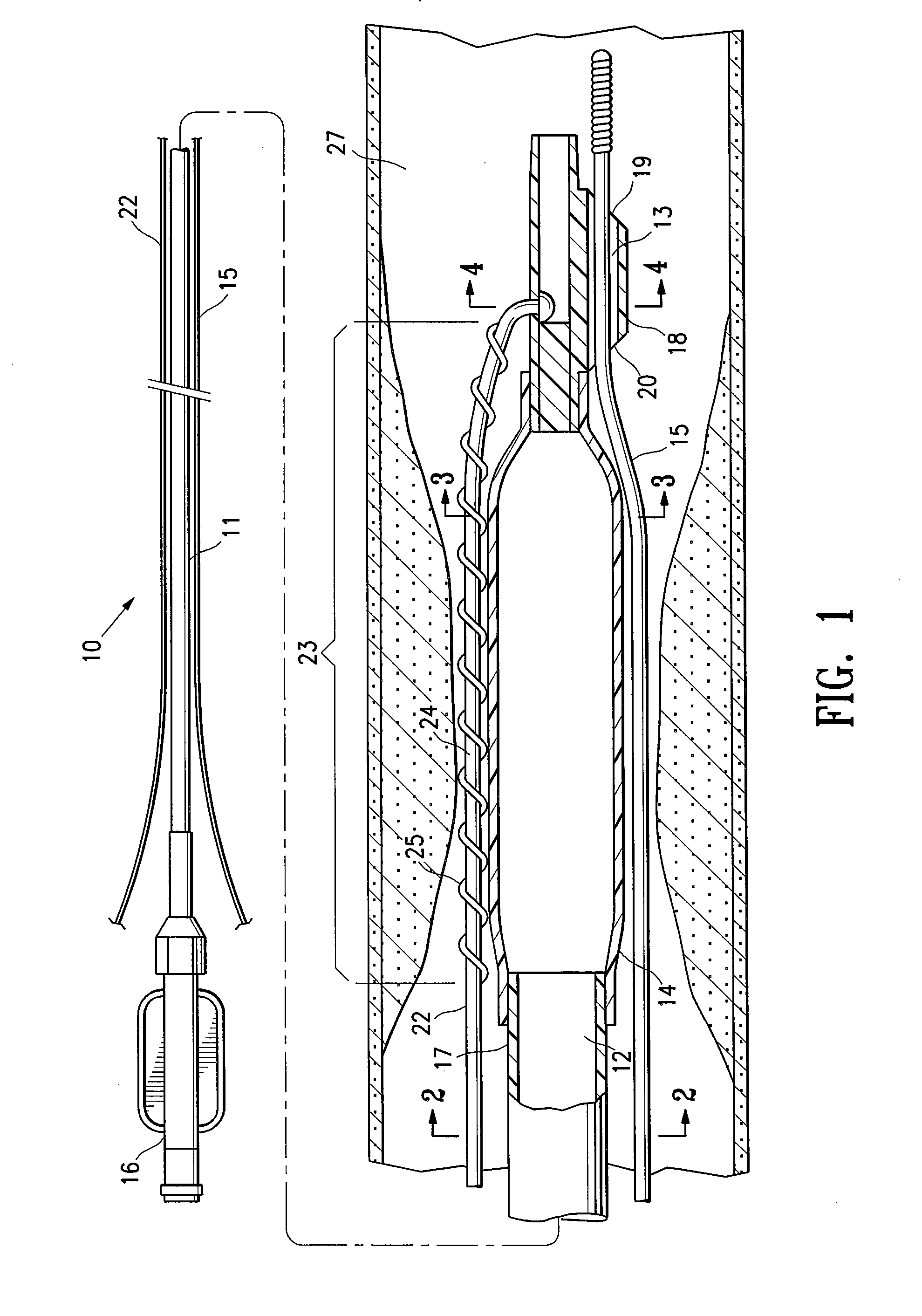
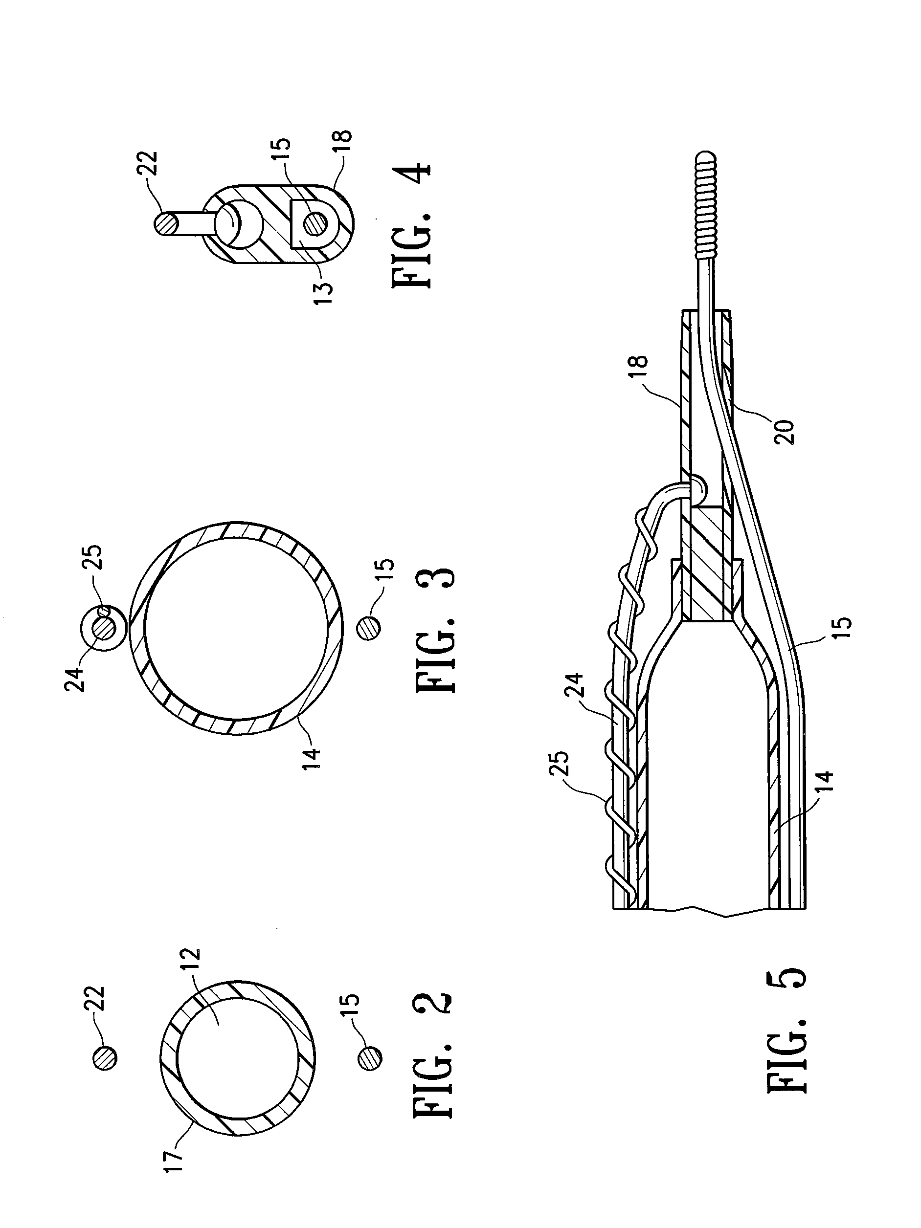
[0022]FIG. 1 illustrates a rapid exchange type balloon catheter 10, generally comprising a shaft 11 with an inflation lumen 12, a guidewire lumen 13 in a distal shaft section configured to slidingly receive a guidewire 15, and a balloon 14 on the distal shaft section. An adapter 16 at the proximal end of catheter shaft 11 is configured to direct inflation fluid into inflation lumen 12, to thereby inflate the balloon 14. FIG. 1 illustrates the balloon 14 in a low profile configuration prior to inflation, for introduction and advancement within the patient's body lumen 27. In use, the distal end of catheter 10 is advanced to a desired region of the patient's body lumen 27 in a conventional manner either over previously positioned guidewire 15, or with guidewire 15 already in the catheter 10. The balloon 14 is inflated to perform a procedure such as dilating a stenosed region of the body lumen, or expanding a stent as discussed in more detail in relation to the embodiment of FIG. 7, an...


PUM


Abstract

This invention is directed to a balloon catheter having at least one advancement wire with a distal end section secured to a distal tip section of the catheter, and with a textured section extending along the outer surface of at least a portion of an inflatable section of the catheter balloon. The textured section of the advancement wire preferably improves the ability of the balloon to remain in position in the patient's body lumen during inflation of the balloon to perform a medical procedure such as balloon angioplasty or stent touch-up.

Description

BACKGROUND OF THE INVENTION [0001] This invention generally relates to catheters, and particularly intravascular catheters for use in percutaneous transluminal coronary angioplasty (PTCA) or for the delivery of stents. [0002] In percutaneous transluminal coronary angioplasty (PTCA) procedures a guiding catheter is advanced in the patient's vasculature until the distal tip of the guiding catheter is seated in the ostium of a desired coronary artery. A guidewire is first advanced out of the distal end of the guiding catheter into the patient's coronary artery until the distal end of the guidewire crosses a lesion to be dilated. A dilatation catheter, having an inflatable balloon on the distal portion thereof, is advanced into the patient's coronary anatomy over the previously introduced guidewire until the balloon of the dilatation catheter is properly positioned across the lesion. Once properly positioned, the dilatation balloon is inflated with inflation fluid one or more times to a...

Claims


Application Information

Patent Timeline
Patent Type & Authority Applications(United States)
IPC IPC(8): A61M29/00A61F2/06A61F2/84A61M25/01A61M25/10A61M29/02
CPCA61F2/958A61F2002/9505A61M25/0102A61M2025/1056A61M2025/0183A61M2025/1004A61M25/104
Inventor LIMON, TIMOTHY A.
Owner ABBOTT CARDIOVASCULAR
Learn More